
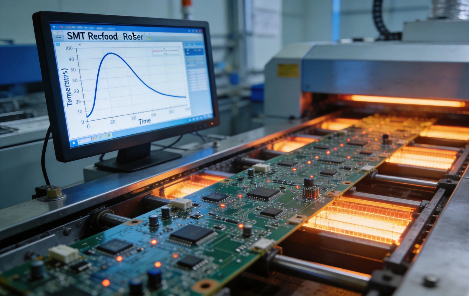
The reflow oven is where the quality of a Smt Assembly run is either confirmed or compromised. After careful paste printing and precise component placement, the reflow profile is the decisive thermal event that transforms a collection of components and Solder Paste into a solid, reliable electronic assembly. Get the profile right, and the joints form cleanly, the components survive intact, and the first-pass yield climbs. Get it wrong, and the consequences range from subtle defects that escape inspection to catastrophic failures that are obvious the moment the board exits the oven.
In a Turnkey Assembly context, the profile is typically developed and qualified by the assembly manufacturer using your board design, their paste inventory, and their oven equipment. Understanding the fundamentals of reflow profiling — what the zones mean, what can go wrong, and what questions to ask your assembly partner — helps you make better design decisions and catch potential problems before they become production issues.
A reflow profile is a time-temperature curve that describes how the assembly heats up, reaches peak temperature, and cools back down as it travels through the reflow oven on a conveyor belt. Understanding each segment of this curve is the foundation for optimizing it.
The preheating zone is the initial ramp from ambient temperature to the soak temperature, typically ranging from room temperature to around 150 to 180 degrees Celsius. The primary objectives during this zone are to evaporate the solvent in the Solder Paste and to bring the board and components up to temperature gradually, avoiding thermal shock to components and minimizing the temperature gradient across the board.
The ramp rate during this zone matters. Too fast a ramp — above roughly 3 degrees Celsius per second — can cause the solvent to vaporize explosively, creating solder balling and splatter. Too slow a ramp — below about 0.5 degrees Celsius per second — allows the board to sit at intermediate temperatures for too long, potentially activating fluxes at temperatures that are too low for proper cleaning action and risking oxidation of the paste.
A controlled ramp rate in the 1 to 2.5 degrees Celsius per second range is generally ideal for most paste formulations and board types.
The soak zone holds the board at an intermediate temperature — typically between 150 and 180 degrees Celsius — for a sustained period before the peak reflow temperature. This zone serves two purposes: it allows the flux in the solder paste to clean the oxide layers from the component leads and pad surfaces, and it helps equalize the temperature across the board so that all joints reach the peak reflow temperature at approximately the same time.
The soak temperature and duration must be calibrated to the specific paste alloy and flux system being used. Leaded pastes (Sn63Pb37) typically have lower soak zone temperatures and shorter soak times than lead-free SAC alloys (SAC305, SAC405). Lead-free pastes with "no-clean" flux systems often have a defined soak window specified by the paste manufacturer that should not be exceeded — too long a soak can deplete the flux activators before the reflow stage, leaving insufficient cleaning action for good wetting.
For boards with large thermal mass variations — for example, a board with a mix of large BGAs and small 0402 passive components — the soak zone becomes especially important for temperature equalization. Without sufficient soak time, the lighter components may reach peak temperature before the heavier ones, leading to uneven wetting and potential component damage.
The reflow zone is where the solder paste transitions from a solid paste to a liquid phase and forms metallurgical bonds with the component termination and the PCB pad. The peak temperature must be high enough to fully melt the solder alloy and achieve good wetting — the formation of a concave fillet that indicates the solder has bonded properly to both surfaces.
For lead-free SAC305 alloy, the typical peak reflow temperature is 240 to 250 degrees Celsius, with a time above liquidus (TAL) of 60 to 90 seconds. The time above liquidus is the period during which the solder is in the liquid phase and active wetting can occur. Too short a TAL produces incomplete wetting and unreliable joints. Too long a TAL — above roughly 120 seconds for most lead-free alloys — increases intermetallic compound (IMC) growth at the joint interface, making the joint brittle over time.
The peak temperature must also stay within the component rating. Most surface mount components are rated to a peak temperature of 260 degrees Celsius, but some are more sensitive — especially plastic QFN and BGA packages with polymer substrate materials, which may have a lower peak temperature limit. The profile must be optimized to achieve sufficient wetting without exceeding the most temperature-sensitive component on the board.
The cooling zone determines the solidification behavior of the solder joint. Controlled cooling — typically at a rate of 2 to 4 degrees Celsius per second — allows the solder to solidify with a fine-grained microstructure that has good mechanical strength and ductility. Slow cooling can cause the solder to solidify with a coarse, brittle microstructure. Too-fast cooling — above about 6 degrees Celsius per second — can create thermal stress in the joint and in the component body, potentially causing cracking in sensitive packages.
For lead-free solders, the cooling rate also affects the tin-silver-copper crystal structure. A properly cooled SAC305 joint has a characteristic fine dispersion of Ag3Sn and Cu6Sn5 intermetallic particles within the beta-tin matrix. An improperly cooled joint may show large primary tin dendrites or a segregated structure that has inferior mechanical properties.
Tombstoning — where a passive component lifts off one termination and stands up on the opposite end like a tombstone — is usually caused by an imbalance in the wetting forces during solder melting. If one termination reaches the liquidus temperature and begins to wet before the other, the surface tension of the liquid solder pulls the component toward the warmer termination, lifting the other end. This is often caused by an uneven temperature distribution across the board during the ramp-to-peak, which in turn is often caused by insufficient soak time or a ramp rate that is too steep for the board's thermal mass.
Manhandling is a less extreme version where the component shifts laterally during reflow, creating a joint that is offset from the pad center. The root causes are similar to tombstoning, and the fix is the same: better thermal uniformity across the board through adjusted ramp rate and soak zone settings.
Solder joint voids — gas pockets trapped within the solder joint — are a persistent concern for area array packages like BGAs and QFNs. Some voiding is inevitable due to the outgassing of flux during reflow. However, excessive voiding — particularly voids greater than 25 percent of the joint area under a BGA — reduces the effective thermal and electrical contact area and can cause the joint to fail under thermal cycling or mechanical shock.
Voiding is influenced by several profile parameters. A steeper ramp rate through the liquidus temperature tends to trap more gas in the joint. A longer soak at temperatures just below liquidus allows the flux to outgas before the solder melts fully, reducing voiding. Some manufacturers add a dedicated pre-reflow annealing soak step specifically to reduce BGA voiding. Vacuum-assisted reflow systems, available in higher-end assembly facilities, can nearly eliminate voids by applying a vacuum during the liquidus phase.
Head-in-pillow is a defect specific to BGA assemblies where the BGA solder ball does not fully merge with the paste deposit on the PCB pad during reflow. The result is a visually deceptive joint — the BGA ball appears to be sitting in the paste deposit, but there is a partial separation at the interface that creates a high-resistance or intermittent connection. HIP defects are notoriously difficult to detect with standard AOI and may pass electrical testing at room temperature but fail under thermal cycling or mechanical flex.
HIP is primarily caused by oxidation of the BGA ball surface or the PCB pad surface before reflow, which prevents the solder from wetting properly. In a Turnkey Assembly context, HIP risk increases when boards or components have been stored for extended periods or handled without proper ESD and moisture protection. Profile adjustments alone cannot fix HIP — the root cause is surface condition, not thermal profile. However, a slightly higher peak temperature or longer TAL can sometimes improve wetting enough to reduce the defect rate when surface oxidation is marginal.
Some components — particularly certain plastic packages, electrolytic capacitors, and some connectors — are sensitive to peak reflow temperature. If the profile overshoots the component rating, the plastic body can crack, the internal die can delaminate, or the moisture already absorbed by the package can vaporize explosively, causing the package to "popcorn."
The standard mitigation for moisture-sensitive components is to bake them before assembly if they have been exposed to humidity, and to ensure the reflow profile does not exceed their rated peak temperature. The IPC/JEDEC J-STD-020 moisture sensitivity level (MSL) classification defines the exposure limits and required bake conditions for each level.
Turnkey assembly often involves boards that combine surface mount components with through-hole components, press-fit connectors, or large heat sinks attached with Thermal Interface Materials. Each of these elements has different thermal requirements, and the profile must be optimized to satisfy all of them simultaneously.
If the board uses a Wave Soldering or Selective Soldering process for through-hole components, the SMT reflow profile is set independently and typically does not need to accommodate the THT process. However, boards that use press-fit connectors — where compliant pins are inserted into plated through-holes without solder — must ensure that the press-fit hole dimensions are not compromised by the SMT reflow. The thermal stress from the reflow profile can cause the plating to recrystallize and lose its press-fit spring properties if the peak temperature is too high.
A board with a large heat sink bolted on during assembly, or with heavy custom connectors that act as heat sinks, creates thermal gradients that make profile optimization more complex. The areas under the heat sink will lag behind the rest of the board during the ramp, meaning that the exposed areas may be at peak temperature while the area under the heat sink is still below liquidus.
The practical fix is to thermocouple the board at multiple locations during profile development — including the most thermally lagging location — and design the profile to ensure that all joints reach the required peak and TAL even at the coolest point. This often means accepting a higher peak temperature or longer TAL than would otherwise be necessary, which must be weighed against the risk of damaging temperature-sensitive components in the warmer areas of the board.
In a turnkey assembly engagement, the assembly manufacturer is responsible for developing and qualifying the reflow profile for your board. Here is how that process typically works and what you should expect from a quality-focused assembly provider.
A qualified assembly house will instrument your board with thermocouples at the critical thermal locations before running the first profile. Standard thermocouple positions include the largest BGA, the largest passive component, the smallest passive component, a through-hole connector if present, and the board center. These thermocouples connect to a data logger that records the actual temperature profile experienced by the board in the oven.
The profile is developed iteratively: an initial profile is run, the thermocouple data is reviewed, and adjustments are made to the oven zone temperatures, conveyor speed, and profile duration until all measured points meet the paste manufacturer specifications and the component ratings.
Once a profile is qualified, it becomes a controlled process parameter. The assembly house should maintain the profile in their process documentation system, run periodic profile verification checks on the oven, and requalify the profile if the board design changes in ways that affect thermal mass — for example, adding components, changing the board thickness, or using a different base material.
You should expect your assembly partner to share the thermocouple profile data from the first article run as part of the first article inspection package. This data is concrete evidence that the board experienced a thermal profile within specification, which is important for reliability qualification and for regulatory compliance in medical, automotive, and aerospace applications.
If your assembly partner switches solder paste formulation — due to availability, cost, or specification changes — the reflow profile may need to be requalified. Paste alloys with different liquidus temperatures (SAC305 vs. SN100C, for example) require different peak temperatures. Even two SAC305 pastes from different manufacturers can have slightly different soak and peak requirements due to differences in the flux chemistry. Your assembly partner should notify you of any paste change and provide updated profile data showing that the new paste is performing within specification on your board.
Several design decisions have an outsized effect on the difficulty of reflow profiling. Making thoughtful choices at the design stage reduces the risk of profile-related defects and gives your assembly partner more latitude to optimize the process.
Designing the board for thermal uniformity — avoiding extreme variations in copper weight, component thermal mass, and board geometry — makes profile optimization easier and reduces the risk of cold joints in the thermally lagging areas. If your board has a very large BGA next to a cluster of small passives, consider whether the thermal mass asymmetry can be reduced by adjusting the copper distribution or component placement.
Components that will have a heat sink attached after assembly should be identified to the assembly house before the first run. Heat sink attachment during assembly can block thermocouple access and create thermal gradients that are not accounted for in the profile qualification. Identifying these components upfront allows the assembly house to plan the profile and thermocouple placement accordingly.
If your BOM includes components rated at MSL Level 2 or higher (more moisture sensitive), build the baking and floor life requirements into your project schedule. Assembling moisture-sensitive components without proper handling can cause popcorn defects that are expensive to repair and may not be detected until later in the test flow. A quality assembly house will have procedures in place for MSL management, but you should confirm this is the case when qualifying a new turnkey partner.
The reflow profile is a deceptively simple-looking curve that represents a complex interplay of thermal mass, paste chemistry, component ratings, and process control. Getting it right requires understanding what each zone of the profile is doing, recognizing the symptoms of common profile-related defects, and working with an assembly partner who has the instrumentation, process discipline, and documentation rigor to develop and maintain a qualified profile over the production run.
The investment in proper profile development and documentation pays for itself many times over in first-pass yield, reduced field failures, and the ability to demonstrate process control during customer qualification or regulatory audits. In a turnkey context, where you rely on the assembly partner to make these process decisions independently, knowing what good process control looks like gives you the foundation to ask the right questions and evaluate the answers you receive.
Contact us to discuss your requirements.
Reliability Standards for Turnkey PCB Assembly in Solar Energy SystemsOctober/16/2026

Turnkey PCB Assembly Insights: 2026 Industry Trends and Market AnalysisMay/26/2026
Quality Control Standards in Turnkey SMT Assembly (IPC-A-610 Explained)July/07/2026

Best Turnkey PCB Assembly for High-Volume Consumer GadgetsOctober/15/2026
Advanced Turnkey SMT Assembly Techniques for High-Density InterconnectsMay/26/2026
Why Transparency is the Key Feature of the Best Turnkey PCB Assembly ProvidersJuly/24/2026
The Impact of Solder Paste Technology on Turnkey SMT Assembly YieldsJuly/29/2026

Best Turnkey PCB Assembly Services: Balancing Cost, Quality, and SpeedJuly/01/2026