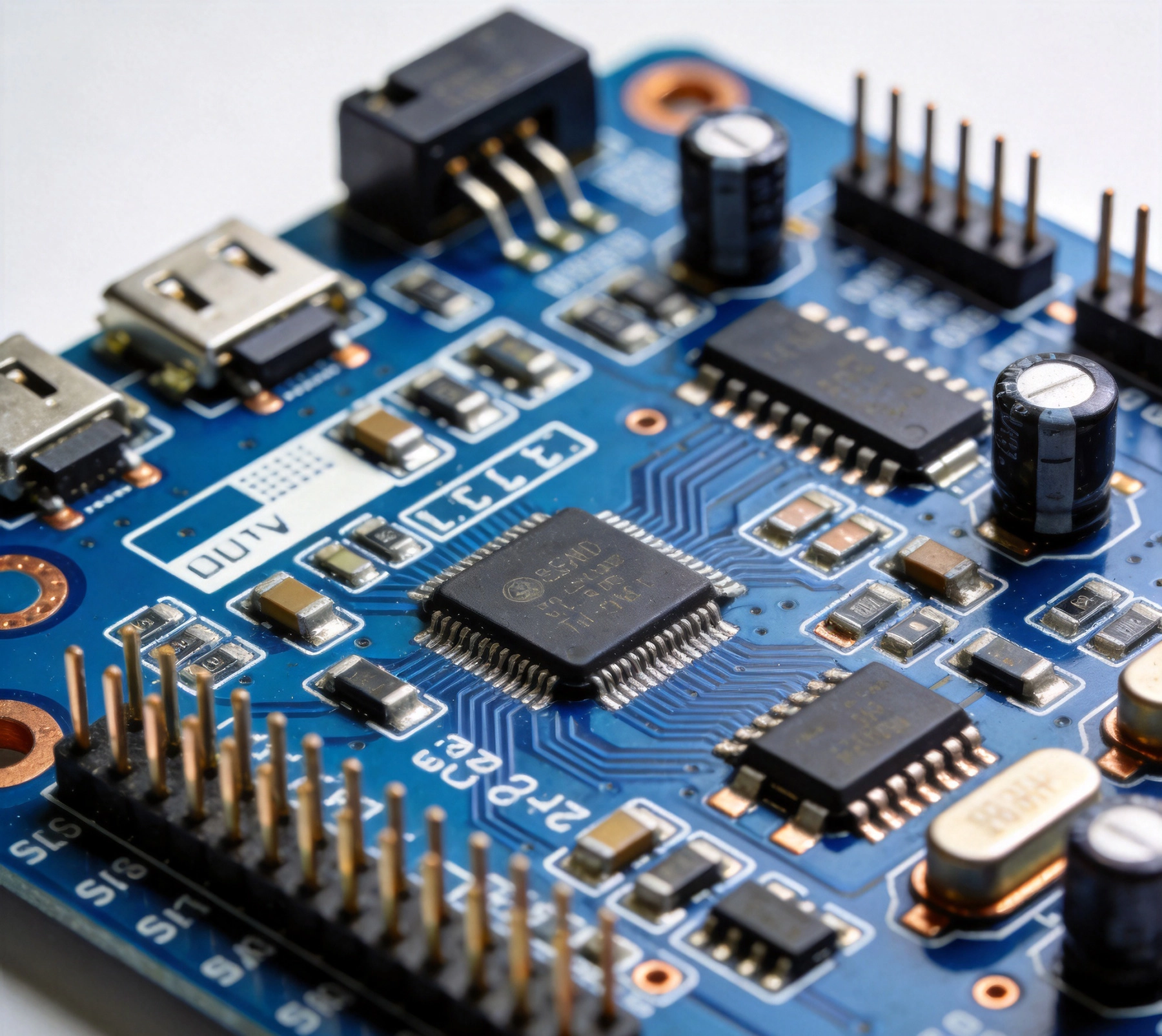
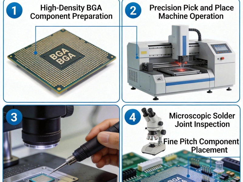
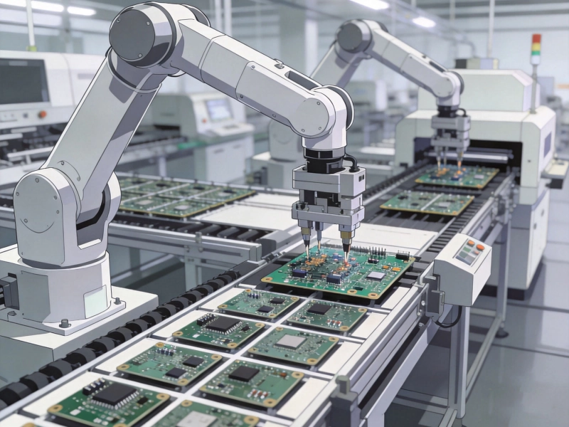
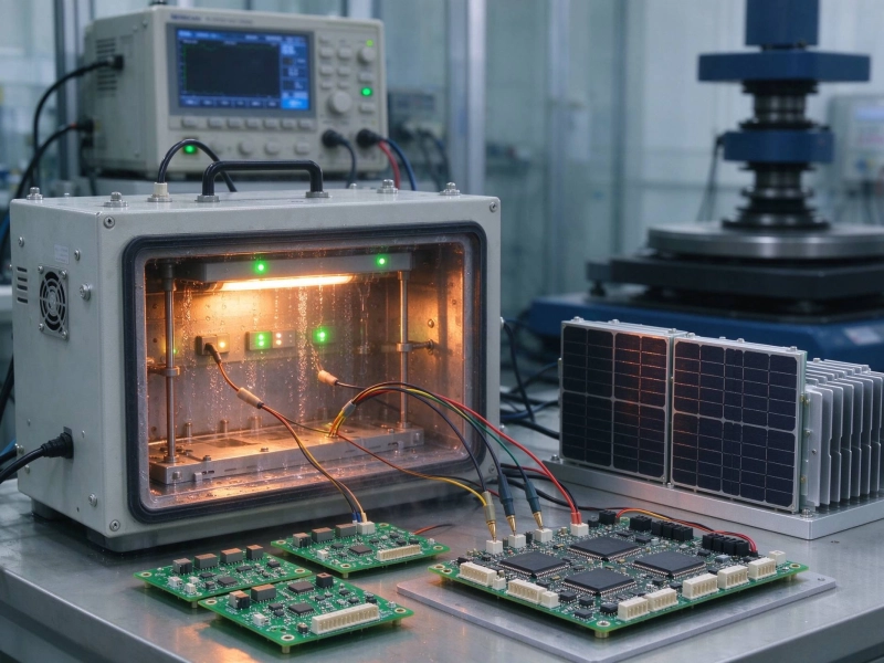
Modern electronics assemblies rarely use only Surface Mount Technology. Connectors need mechanical strength that through-hole provides. Power components need leads that dissipate heat through the board. Sensor modules need headers that survive repeated mating cycles. Mixed technology boards—combining SMT and through-hole components on the same substrate—are the rule, not the exception.
Assembling these hybrid boards presents challenges that pure SMT doesn't. You need processes that handle both component types, equipment that accommodates different placements, and expertise in managing the interaction between technologies. This guide covers everything you need to know about turnkey Smt Assembly for mixed technology boards.
Why Mixed Technology Boards Still Matter
With SMT dominating Electronics Assembly, why do through-hole components persist? Several reasons make through-hole technology irreplaceable in many applications:
Mechanical Robustness
Through-hole components create permanent, high-strength connections. The component leads pass completely through the PCB, creating a mechanical bond that SMT simply can't match. This matters for:
-
Connectors: USB, HDMI, and other connectors experience repeated mechanical stress. Through-hole mounting ensures they don't loosen over time.
-
High-current paths: Power inductors, transformers, and high-current connectors need the robust connection through-hole provides.
-
Board-level connectors: Daughtercards, modules, and stackable systems rely on through-hole headers for reliable board-to-board connections.
-
Applications with vibration: Automotive, industrial, and aerospace environments subject assemblies to continuous vibration. Through-hole components handle this stress better.
Thermal Management
Through-hole leads conduct heat from the component body into the PCB more effectively than SMT terminations. For power components that generate significant heat, through-hole mounting provides better thermal pathways to heatsinking planes.
Accessibility and Repairability
Through-hole components are easier to replace during rework or repair. A technician can remove and reinstall a through-hole part with conventional tools—a factor that matters for industrial equipment, military systems, and any application where field service is anticipated.
Component Availability
Some components simply aren't available in SMT packages. Large electrolytic capacitors, heavy transformers, electromechanical switches, and certain connectors only come in through-hole versions. Designing for mixed technology is often the only practical option.
The Two Approaches to Mixed Technology Assembly
When assembling boards with both SMT and through-hole components, manufacturers typically choose between two process flows. The right approach depends on your board design, components, and quality requirements.
Approach 1: SMT First, Then Through-Hole
The most common sequence places SMT components first, followed by through-hole insertion and soldering. Here's why this sequence usually works best:
-
SMT Reflow Soldering happens at high temperatures that could damage some through-hole components
-
Through-hole components often have plastic bodies that can't survive reflow temperatures
-
Inserting through-hole parts after SMT keeps them accessible for manual touch-up if needed
The process flow:
-
SMT paste application
-
SMT component placement
-
SMT Reflow Soldering
-
Through-hole component insertion
-
Wave Soldering or selective soldering
-
Cleaning and inspection
Approach 2: Separate Assembly Operations
For complex boards with temperature-sensitive through-hole components or unusual requirements, separate assembly operations may be necessary:
-
Some through-hole components (certain connectors, switches) may require special handling
-
Boards with both SMT and press-fit through-hole components can avoid soldering entirely for the THT parts
-
Some applications require manual soldering of through-hole components after Smt Assembly
This approach adds cost and cycle time but provides maximum flexibility for complex assemblies.
Wave Soldering: The Traditional Method
Wave Soldering has been the workhorse of through-hole assembly for decades. Understanding its capabilities and limitations helps you design boards that work with this process.
How Wave Soldering Works
In wave soldering, molten solder is pumped to create a standing wave. The PCB passes over this wave, with the bottom surface contacting the solder. Capillary action draws solder up through the plated through-holes, creating connections to component leads.
Modern wave solder systems include:
-
Flux application: Spray or foam fluxing prepares surfaces for soldering
-
Preheating: Gradual heating prevents thermal shock and activates flux
-
Solder wave: Typically a dual-wave configuration: turbulent wave for hole fill, smooth wave for cosmetic joint finish
-
Cooling: Controlled cooling prevents thermal stress and cold joints
Wave Soldering Advantages
-
High throughput—suited for high-volume production
-
Well-established process with extensive expertise available
-
Lower equipment cost than selective solder systems
-
Handles a wide variety of component types and board sizes
Wave Soldering Limitations
-
All bottom-side through-hole components are soldered simultaneously
-
SMT components on the bottom side may be at risk (requires glue adhesive)
-
Large thermal mass components may not solder properly
-
Higher solder consumption and potential for bridging
-
Limited control over individual joint parameters
Designing for Wave Soldering
Wave-solder-compatible designs require attention to:
-
Component orientation: All components should face the same direction to facilitate soldering
-
Thermally heavy parts: Large ground planes, heat sinks, and battery holders may not reach solder temperature
-
SMD on bottom: Requires adhesive to hold components during wave contact
-
Keepout zones: Connectors and components that shouldn't be soldered need careful placement
Selective Soldering: Precision for Complex Boards
Selective soldering has largely replaced wave soldering for complex mixed-technology boards. This process solders through-hole components individually or in small groups, providing precise control that wave soldering can't match.
How Selective Soldering Works
Selective solder systems use a programmable nozzle to apply solder exactly where needed. The process typically follows these steps:
-
Flux is applied only to through-hole locations (spray, micro-droplet, or foam)
-
The board is preheated to bring it to uniform temperature
-
A solder pot nozzle positions over each through-hole or group of holes
-
Molten solder is pumped through the nozzle, filling the hole
-
The process moves to the next location, repeating until complete
Selective Soldering Advantages
-
Precision: Solder only where you need it, avoiding damage to nearby components
-
SMT-safe: Can solder through-hole near temperature-sensitive SMT components
-
Programmable: Each joint can have unique parameters (solder volume, contact time, preheat)
-
No adhesive needed: SMT components on the bottom don't require adhesive fixation
-
Reduced solder consumption: Only uses solder where required
Selective Soldering Limitations
-
Lower throughput than wave soldering
-
Higher equipment cost
-
Requires more programming and setup time
-
Very large or heavy components may need special handling
When to Choose Selective Soldering
Selective soldering is the right choice when:
-
Your board has SMT components near through-hole components
-
You have thermally sensitive parts that wave soldering could damage
-
You need to solder a subset of through-hole components while leaving others unsoldered (press-fit)
-
Board density requires precise solder placement to avoid bridging
-
You have mixed metal finishes (HASL board with ENIG components)
Press-Fit Technology: Solderless Alternative
Press-fit technology offers an alternative to soldering for through-hole connections. Instead of solder, specially designed pins are pressed into plated through-holes with an interference fit that creates reliable electrical and mechanical connections.
How Press-Fit Works
Press-fit pins have a compliant section (often a cross or split design) that deforms as it's inserted into the plated hole. The interference between the pin and hole wall creates gas-tight contact without solder. The connection is:
-
Mechanically robust—comparable to solder joints
-
Gas-tight—preventing oxidation and maintaining contact resistance
-
Repairable—the pin can be extracted and replaced if needed
Press-Fit Advantages
-
No solder process required—eliminates thermal stress and solder defects
-
Excellent for mixed-technology boards with temperature-sensitive components
-
Lower assembly cost in high volumes (no solder, no flux, no cleaning)
-
Environmentally friendlier—no solder dross or flux waste
-
Ideal for boards that will be disassembled for repair or recycling
Press-Fit Considerations
-
Requires specially designed pins—standard component leads won't work
-
Hole plating quality is critical—the connection depends on proper plating thickness
-
Insertion force requirements may need specialized equipment
-
Not suitable for all through-hole component types
Common Press-Fit Applications
Press-fit technology is popular for:
-
Board-to-board connectors
-
Backplane connections in telecommunications equipment
-
Automotive Electronics requiring high reliability
-
Applications requiring field replaceability
Turnkey Assembly Services: What They Cover
Turnkey SMT assembly for mixed technology boards packages multiple services into a single engagement. Understanding what's typically included helps you evaluate quotes and plan your project.
Services Usually Included
-
PCB Fabrication: Manufacturing the bare circuit boards to your specifications
-
Component procurement: Sourcing all components from authorized distributors
-
SMT assembly: Paste printing, component placement, and reflow soldering
-
Through-hole assembly: Component insertion and soldering (wave or selective)
-
Testing: In-circuit test, functional test, or both
-
Conformal Coating: Optional protective coating application
-
Box-build: Final assembly including enclosures, cables, and subsystems
What's Sometimes Included
What's Usually Extra
-
Engineering changes after production begins
-
Rush order premiums
-
Special packaging or labeling requirements
-
Regulatory certification (FCC, CE, UL testing)
-
Component substitutions when originals are unavailable
Design for Mixed Technology Assembly
Your design decisions have enormous impact on manufacturability, cost, and quality. Following Dfm principles for mixed technology boards prevents problems before production begins.
Component Placement Guidelines
SMT Placement
-
Place SMT components on the top side as your primary surface
-
Bottom-side SMT requires adhesive if using wave soldering
-
Keep SMT components away from through-hole insertion points
-
Allow adequate clearance around tall through-hole components for wave or selective solder access
Through-Hole Placement
-
Group through-hole components in accessible areas
-
Consider hand-fitting space around large connectors for solder iron touch-up
-
Place components requiring post-solder cleaning accessibly
-
Thermally heavy parts (large caps, transformers) should be placed early in the soldering sequence
Thermal Considerations
-
Identify all temperature-sensitive components and ensure they're protected from solder process heat
-
Large copper areas under through-hole pads act as heat sinks—may need increased thermal clearance
-
Battery holders and plastic connectors may have maximum temperature ratings below solder process temperatures
-
Consider the order of assembly when thermally sensitive parts are present
Pad and Hole Design
-
Follow Ipc Standards for pad sizes and plating requirements
-
Ensure through-hole barrel plating meets thickness specifications for reliable solder joints
-
Consider solder mask between pads to prevent bridging
-
Press-fit holes require specific plating thickness ranges—communicate requirements clearly
Quality Control for Mixed Technology Boards
Mixed technology boards require quality control attention at multiple stages, with special focus on through-hole solder joints that are harder to inspect than SMT terminations.
Visual Inspection
Automated Optical Inspection (AOI) handles most SMT inspection. Through-hole joints require manual visual inspection or specialized systems:
-
IPC-A-610 workmanship standards define acceptable solder joint criteria
-
Through-hole fill requirements vary by application (typically 75-100% hole fill)
-
Training inspectors to recognize common through-hole defects is essential
X-Ray Inspection
For BGAs and other components with hidden connections, X-ray inspection reveals defects invisible to optical inspection. While primarily used for SMT, X-ray can also verify through-hole fill in certain configurations.
Automated Test
In-circuit test (ICT) verifies every component is present and correct. For through-hole components, ICT fixtures use spring-loaded probes that contact test points or component leads:
-
Fixture cost is significant but justified for high volumes
-
Boundary scan can test JTAG-compatible devices without physical probe access
-
Flying probe testing offers lower cost for prototypes and low volumes
Functional Test
ICT passes if components are correct, but functional test verifies the board actually works:
-
Power-up tests verify basic operation
-
Functional tests exercise board functions under various conditions
-
Burn-in testing exposes early failures by operating boards at elevated temperature
Finding the Right Turnkey Assembly Partner
Not all contract manufacturers handle mixed technology assemblies well. Evaluating potential partners requires understanding what questions to ask and what to look for.
Critical Capabilities
-
Selective solder equipment: Can they handle your board complexity?
-
Wave solder capability: Do they have wave soldering for simpler high-volume boards?
-
Press-fit equipment: If you need press-fit, do they have insertion equipment?
-
Test capability: Can they develop and build the test fixtures you need?
-
Box-build experience: If your product includes cables and enclosures, can they handle final assembly?
Questions to Ask
-
What's your minimum order quantity for mixed technology boards?
-
Do you prefer wave or selective soldering, and why?
-
How do you handle temperature-sensitive through-hole components?
-
What's your typical first-pass yield for mixed technology assemblies?
-
Can you provide first article inspection reports?
-
What happens if we need engineering changes mid-production?
-
What's your quality certification (ISO 9001, AS9100, etc.)?
Red Flags
-
Unable or unwilling to visit their facility
-
Vague answers about their through-hole process
-
No examples of similar assemblies they've completed
-
Quote significantly lower than other providers without explanation
-
Resistance to your quality or test requirements
Common Challenges and Solutions
Mixed technology assembly presents predictable challenges. Knowing what to expect helps you plan and prevent problems.
Challenge: Tombstoning Near Through-Hole Components
Problem: SMT components adjacent to through-hole holes may tombston (one end lifts) during reflow due to uneven heating or solder wicking.
Solutions:
-
Add thermal relief connections to through-hole pads
-
Adjust component placement to increase clearance
-
Modify reflow profile to reduce thermal gradient
Challenge: Solder Bridging
Problem: Solder bridges form between adjacent through-hole pins, especially with fine-pitch connectors.
Solutions:
-
Use solder mask between pins
-
Switch from wave to selective soldering for sensitive areas
-
Adjust solder pot temperature and contact time
Challenge: Component Damage from Soldering Heat
Problem: Plastic-bodied components near soldering operations may melt, warp, or have their internal characteristics changed.
Solutions:
-
Use selective soldering instead of wave
-
Add heat shielding or copper heat sinks to protect sensitive parts
-
Rearrange assembly sequence to install heat-sensitive parts last
Challenge: Press-Fit Pin Insertion Damage
Problem: Improperly inserted press-fit pins can crack PCB vias or create unreliable connections.
Solutions:
-
Verify PCB manufacturer meets plating specifications
-
Use proper insertion equipment with controlled force
-
Include press-fit verification in QC process
Cost Optimization Strategies
Mixed technology assembly is more expensive than pure SMT. However, several strategies can reduce costs without compromising quality.
Design Optimization
-
Minimize through-hole count by using SMT alternatives where available
-
Select through-hole components with compatible pin diameters to reduce insertion time
-
Standardize on connector types to reduce changeover time
Process Optimization
-
Batch similar boards together to reduce setup time
-
Use wave soldering for high-volume, simple through-hole content
-
Reserve selective soldering for complex boards that need it
-
Eliminate unnecessary cleaning steps if no-clean processes are acceptable
Volume Strategies
-
Long-term agreements lock in pricing and ensure capacity
-
Order quantities that match panel efficiency reduce per-unit cost
-
Consignment of expensive components reduces CM inventory carrying cost
Conclusion
Mixed technology assembly combining SMT and through-hole components is a fact of life for most electronic products. The mechanical robustness, Thermal Management, and component availability advantages of through-hole technology ensure it remains essential despite SMT's dominance.
Successfully assembling mixed technology boards requires understanding your options—wave soldering, selective soldering, and press-fit technology—then choosing the right approach for your specific board and requirements. It demands attention to Design For Manufacturing, quality control throughout the process, and partnership with an experienced Contract Manufacturer.
The investment in proper mixed technology assembly pays dividends in reliability, serviceability, and the ability to use the best components for each application. As your product moves from Prototype To Production, take the time to optimize your design for manufacturability and select a turnkey partner who can deliver quality at scale.
Frequently Asked Questions
Can all through-hole components be soldered with selective soldering?
Most through-hole components work well with selective soldering. However, very large components with high thermal mass may not reach solder temperature even with extended contact time. Connectors with many pins may be slower to solder than selective soldering is practical for. Your CM should advise on any limitations for your specific components.
What's the minimum order quantity for mixed technology PCB assembly?
Minimum order quantities vary by manufacturer. Some turnkey services accept orders as low as 5-10 units for prototypes. Production MOQs typically start at 100-500 units, though this varies based on board complexity and the services required. Discuss your requirements with potential partners to find the right fit.
How do I know if my board should use wave or selective soldering?
Wave soldering suits high-volume boards with relatively simple through-hole content and no temperature-sensitive SMT components on the bottom side. Selective soldering is better for complex boards with mixed technology, SMT near through-hole components, or boards requiring precise solder placement. Many manufacturers use both processes depending on board requirements.
What's the typical lead time for mixed technology assembly?
Lead times vary by complexity and CM capacity. Simple boards with standard components might take 2-3 weeks from order to delivery. Complex boards requiring custom test fixtures, long-lead components, or special processes can take 6-10 weeks. Factor in additional time for first article qualification if you're using a new design.
How do I prevent solder defects in through-hole joints?
Preventing defects starts with design: appropriate pad sizes, proper hole diameters, adequate plating thickness. Process control matters too: correct flux application, appropriate preheat temperatures, proper solder pot temperature and contact time. Inspection and test catch defects that escape process control. Work with your CM to establish parameters and monitor them throughout production.
Need help planning your mixed technology Pcb Assembly? Our engineering team can review your design and recommend the optimal assembly approach.