
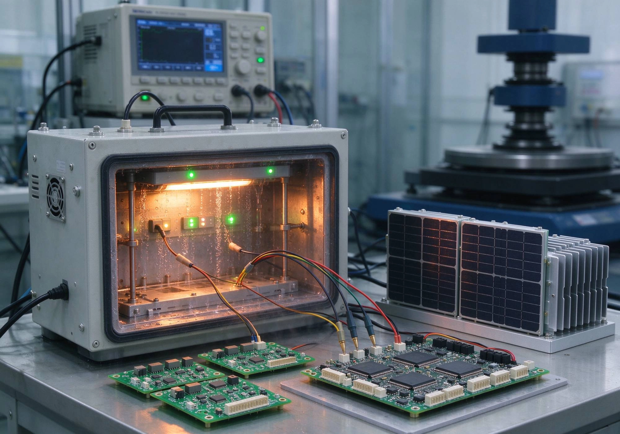
Solar energy systems don't forgive sloppy electronics. A single cold solder joint on an inverter control board, a thin copper trace on a DC-DC converter, or a poorly specified Conformal Coating can turn a twenty-year warranty into a costly field failure. That's why reliability standards for Turnkey PCB Assembly in solar energy systems matter far more than unit price alone. This article walks through the key IPC, IEC, and safety standards that govern solar Pcb Assembly, explains what Class 2 versus Class 3 really means in practice, and shares practical lessons from real manufacturing experience so you can evaluate a turnkey supplier with confidence.
Solar Power Electronics — including inverters, charge controllers, MPPT modules, battery management systems, and combiner box electronics — operate under conditions that would destroy a typical consumer-grade PCB. They face wide temperature swings, high humidity, salt spray in coastal installations, continuous UV exposure, and in many cases, system voltages reaching 1000 V or 1500 V DC. A board that passes basic functional testing in a climate-controlled factory can still fail within months once deployed on a rooftop in Arizona or a ground-mount array in Southeast Asia.
From our experience assembling PCBA for solar inverters and energy storage systems, the most common failure modes we see are:
These aren't theoretical risks. They are the exact reasons why standards exist — and why a Turnkey PCB Assembly partner must understand them deeply, not just tick boxes on a checklist.
The Ipc Standards framework is the foundation of electronic assembly quality worldwide. For solar applications, the following standards are most relevant:
IPC-A-610 (current version J, released 2023/2024) is the most widely used visual acceptance standard for electronic assemblies. It defines three product classes:
Most commercial and utility-scale solar inverters are built to IPC Class 2 as a minimum, with Class 3 applied to specific high-voltage or safety-critical sub-assemblies. The difference between Class 2 and Class 3 is not cosmetic — it affects hole copper thickness (20–25 µm for Class 3 vs. 18–20 µm for Class 2), solder void limits, via fill requirements, and inspection rigor.
J-STD-001 (current version H/J) defines the materials, methods, and acceptance criteria for soldered interconnections. For solar PCBA, key requirements include proper Solder Paste selection for lead-free alloys, controlled reflow profiles, and verification of wetting on OSP, ENIG, or HASL finishes. Power devices with large thermal pads demand particular attention — voiding should be held below 15% for Class 2 and below 8% for Class 3, with vacuum reflow recommended for critical applications.
While IPC-A-610 governs the assembled board, IPC-6012 (current version F, 2023) governs the bare PCB itself. Solar boards often require high-Tg基材 (Tg ≥ 170°C), Thick Copper (2–6 oz for power layers), and enhanced dielectric strength. IPC-6012 Class 3 mandates stricter tolerances on copper thickness, via plating, and thermal stress resistance — all of which directly impact long-term reliability under thermal cycling.
This standard covers the visual inspection of bare PCBs, including pad condition, solder mask registration, and annular ring requirements. For high-voltage solar boards, solder mask integrity is especially important because any pinhole or thin spot in a high-voltage isolation zone can become a failure point.
Ipc Standards cover assembly quality, but solar Power Electronics must also comply with IEC safety and performance standards. These standards directly influence PCB layout and assembly decisions:
IEC 62109-1/-2 is the core safety standard for PV inverters and power conversion equipment. It mandates minimum creepage and clearance distances based on system voltage, pollution degree, and material group. For a 1500 V DC system in an outdoor Pollution Degree 2 environment, IEC 62109 requires a minimum of 8.0 mm creepage and 6.0 mm clearance between high-voltage and low-voltage circuits.
In practice, this means the assembly house must respect isolation slots milled into the PCB, avoid bridging isolation barriers with solder mask or conformal coating drips, and ensure that component lead forming does not violate clearance through the board thickness. We've seen certification failures caused simply because a technician routed a wire harness across an isolation slot during final assembly — the PCB itself was fine, but the assembled unit failed.
IEC 61215 covers design qualification and type approval for terrestrial PV modules, while IEC 61730 addresses PV module safety qualification. Although these standards primarily govern the module level, they influence the reliability expectations for any electronics integrated into or near the module, such as optimizers, microinverters, and junction box PCBs.
IEC TS 63157 provides Quality Assurance guidelines specifically for the manufacture of power conversion equipment used in PV systems. It assumes an ISO 9001 quality management system is in place and adds requirements for documented product properties, manufacturing consistency, and warranty-related performance confidence. This standard is increasingly referenced by certification bodies during factory audits.
While focused on installation and maintenance, IEC TS 63049 reinforces the importance of quality-assured components throughout the PV system lifecycle. A Turnkey Pcba supplier that can demonstrate compliance traceability supports downstream certification under this framework.
Knowing the standards is one thing. Executing them consistently across hundreds or thousands of boards is another. Here are the manufacturing controls we consider non-negotiable for solar Turnkey Assembly:
Solar PCBA deployed outdoors or in unconditioned enclosures almost always requires conformal coating. Key considerations:
A qualified solar PCBA should pass the following tests before shipment:
When evaluating a turnkey supplier for solar energy systems, look beyond price per unit. Ask these questions:
One thing we've learned the hard way: a supplier that says "yes" to everything without asking clarifying questions about your system voltage, operating environment, and certification targets is probably not the right partner. A good turnkey assembler will push back on design choices that compromise reliability — like placing a large electrolytic capacitor too close to a hot IGBT, or routing a sensitive analog trace parallel to a switching node.
Building reliable solar energy electronics requires more than good design — it demands disciplined execution against recognized standards. The key takeaways are:
If you're sourcing turnkey Pcb Assembly for a solar inverter, optimizer, or energy storage project, don't settle for a generic electronics manufacturer. Look for a partner who speaks the language of IPC-A-610, IEC 62109, and thermal cycling profiles — because in solar, reliability isn't a feature, it's the product.
Class 2 allows limited defects and is suitable for most commercial solar inverters. Class 3 has stricter requirements on copper thickness, via reliability, and solder quality, and is used for mission-critical or harsh-environment applications. The choice depends on system voltage, expected lifetime, and failure consequences.
Yes. Conformal coating can reduce required clearance distances under certain conditions, but the coating type, thickness, and application method must be specified on the assembly drawings and verified during certification. Not all coatings qualify — check with your certification body.
For IPC Class 2, voiding below 15% is generally acceptable. For Class 3 or critical power devices (IGBTs, SiC MOSFETs), aim for below 8%, using vacuum reflow if necessary. Always validate with X-ray inspection.
A minimum of 48 hours at rated load is recommended, with continuous monitoring of output waveforms, temperature rise, and protection functions. Some manufacturers extend this to 72 hours for premium products.
Yes, and this is often preferable for solar applications because it ensures material traceability, consistent quality control, and single-point accountability. Verify that the supplier holds relevant certifications (ISO 9001, UL recognition, Iatf 16949 if applicable) and can provide full documentation packages for certification submissions.
Best Turnkey PCB Assembly Services: Balancing Cost, Quality, and SpeedJuly/01/2026
Why Transparency is the Key Feature of the Best Turnkey PCB Assembly ProvidersJuly/24/2026
Turnkey SMT Assembly: Handling 01005 Components and Micro BGAsJune/08/2026

Turnkey PCB Assembly Insights: 2026 Industry Trends and Market AnalysisMay/26/2026

Turnkey PCB Assembly Insights: The Shift Towards High-Mix Low-Volume ProductionJuly/02/2026
Turnkey SMT Assembly for Mixed Technology Boards (SMT + Through-Hole)September/04/2026
The Impact of Solder Paste Technology on Turnkey SMT Assembly YieldsJuly/29/2026
Optimizing Reflow Profiles for Flawless Turnkey SMT AssemblySeptember/30/2026