
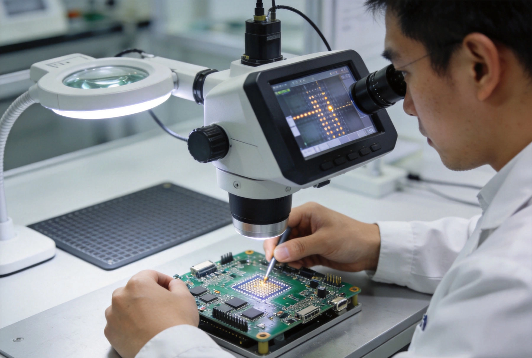
When you commission a turnkey Smt Assembly, you're entrusting your product's manufacturing quality to a third party. How do you know whether the boards you receive meet acceptable standards? How do manufacturers ensure consistency across thousands of assemblies? How do buyers and sellers communicate quality expectations without endless arguments about what constitutes an acceptable solder joint? The answer to all these questions centers on a single document: IPC-A-610, the most widely recognized Electronics Assembly workmanship standard in the world.
Understanding IPC-A-610 transforms the procurement conversation from subjective opinions ("that joint looks bad to me") into objective criteria ("that joint violates IPC-A-610 Section 3.4.2 minimum wetting requirement"). This article explains what IPC-A-610 covers, how it structures quality expectations, and what it means for anyone specifying or receiving turnkey SMT Assembly Services.
IPC-A-610, titled "Acceptability of Electronic Assemblies," is an industry-developed standard published by IPC (formerly the Institute of Printed Circuits, now simply IPC). The standard defines visual acceptance criteria for electronic assemblies—essentially, what a properly assembled board looks like and where the boundary lies between acceptable and defective workmanship.
The standard emerged from industry collaboration because electronics manufacturers needed a common language for quality expectations. Without shared criteria, every manufacturer defined quality differently, every customer judged boards by different standards, and disputes about acceptability consumed enormous time and resources. IPC-A-610 provided the consensus solution: documented, illustrated criteria that manufacturers and customers could reference when evaluating assembly quality.
IPC-A-610 is revised on a three-year cycle, with the current revision reflecting advances in component technology, assembly processes, and industry best practices. When specifying IPC-A-610 compliance, always reference the specific revision year—IPC-A-610 Rev F differs from Rev J in ways that may matter for your application. The revision date matters because standards evolve as the industry learns and new components create new acceptability questions.
One of IPC-A-610's most important concepts is its classification system. The standard recognizes three distinct application classes, each with different quality expectations reflecting the consequences of field failure.
Class 1: General Electronic Products
Class 1 covers electronic products where the primary concern is function—boards that simply need to work, without particular demands for extended service life or uninterrupted operation. Consumer Electronics, toys, some computer peripherals, and budget-oriented products typically fall into Class 1. The acceptability criteria here are the most lenient, allowing cosmetic imperfections that wouldn't affect board function.
A Class 1 board might ship with minor solder splash, slight component marking obliteration, or small scratches on the board surface. These conditions would be unacceptable in stricter classes but are permitted in Class 1 because they don't affect the board's ability to function. When your turnkey quote references Class 1, understand that you're accepting a relatively broad range of cosmetic variation.
Class 2: Dedicated Service Electronic Products
Class 2 applies to electronic assemblies where continued performance and uninterrupted service are important, but some downtime is acceptable. Industrial controls, telecommunications equipment, medical devices that don't implant, and computer servers typically qualify for Class 2. The criteria here are more stringent—cosmetic defects receive more scrutiny, and the acceptable range of variation narrows considerably.
A Class 2 board cannot ship with component damage that might affect reliability, solder joints with marginal wetting, or contamination that could create long-term reliability risks. These boards must perform reliably throughout their intended service life, even if that service life involves environmental stress, thermal cycling, or vibration exposure. Most turnkey SMT quotes default to Class 2 unless otherwise specified.
Class 3: High-Performance/Harsh Environment Electronic Products
Class 3 covers assemblies where continued performance is critical and any failure could create safety risks or cause significant economic loss. Aerospace systems, military electronics, medical implant devices, and industrial safety equipment fall into this category. Class 3 acceptance criteria are the most demanding—almost no cosmetic variation is permitted, and every deviation from ideal workmanship receives careful scrutiny.
Class 3 boards must meet the highest standards of component placement accuracy, solder joint quality, and cleanliness. The cost of meeting Class 3 requirements exceeds Class 2 costs, sometimes substantially. When turnkey manufacturers quote for Class 3 work, they factor in the additional inspection time, process controls, and documentation that Class 3 demands. If your application truly requires Class 3, budget accordingly—attempting to negotiate Class 3 quality at Class 2 pricing creates friction that damages procurement relationships.
IPC-A-610 addresses dozens of SMT-specific conditions. Understanding the categories most relevant to Turnkey Assembly helps buyers evaluate whether their boards meet expectations.
Component placement accuracy is measured relative to the component body and its solder pads. IPC-A-610 defines maximum offsets in both the X-axis (along the length of the component) and rotational alignment. For most rectangular chip components (resistors, capacitors), Class 2 allows the component body to overhang one end of the pad by up to 50% of the pad width, provided the solder joint meets wetting requirements. Greater overhang may be classified as a defect.
For SOIC, QFP, and similar gull-wing packages, the criterion shifts to lead inspection: leads must touch the pad surface, with no visible uplift, and the fillet must show proper wetting on at least three sides of each lead. QFN and BGA packages receive separate treatment, as their bottom-terminated connections aren't visible for direct solder joint inspection.
The heart of IPC-A-610 lies in solder joint assessment. The standard defines three quality levels for joints: Target (ideal), Acceptable (meets minimum requirements), and Defect (fails to meet requirements).
For surface mount solder joints, the standard evaluates multiple factors. Wetting—the extent to which molten solder flows and bonds to component leads and pad surfaces—represents the primary quality indicator. A properly wetted joint shows shiny, smooth solder fillets that coat the metal surfaces with no visible dewetting or non-wetting areas. Acceptable wetting may show some variation in surface texture, particularly for lead-free solders, but obvious defects like grainy surfaces, voids visible from the surface, or non-wetted metal areas constitute rejection criteria.
Fillet shape and coverage matter equally. A proper SMT fillet shows continuous solder coverage along the component lead-pad interface, with a concave profile that indicates proper solder volume. Convex fillets may indicate insufficient solder, while fillets with visible holes or voids may indicate gas entrapment during reflow.
Tombstoning occurs when one end of a two-terminal chip component lifts during reflow, leaving the other end still attached to its pad. The component sits upright on the board, resembling a tombstone. IPC-A-610 addresses tombstoning by specifying that any component showing significant lift constitutes a defect. Minor lift may be acceptable under certain conditions, but in practice, tombstoning components typically require rework.
Skip welding—the failure of a solder joint to form properly—represents another common defect category. This manifests as insufficient solder, cold solder joints, or joints where the solder never properly melted and flowed. The root causes range from insufficient paste volume to contamination on pad surfaces to improper reflow temperature profiling.
Voids in solder joints—gas pockets trapped within the solder during reflow—receive specific attention in IPC-A-610. While some voiding is acceptable, excessive voiding weakens joint mechanical strength and may affect thermal or electrical performance. The standard defines maximum allowable void percentages for different joint types, though exact limits vary by revision and specific joint category.
Solder balls—small spheres of solder that separate from the main joint and rest on the board surface—represent another defect category. IPC-A-610 permits small solder balls under specific conditions for some classes, but rejects others based on ball size, location, and proximity to exposed conductors. Solder balls near component leads or connector pads are particularly scrutinized because they may create unintended connections.
IPC-A-610 specifies cleanliness requirements for assembled boards. Flux residue, while expected from most soldering processes, cannot exceed levels that might affect long-term reliability. The standard references IPC standard IPC-9201 for guidance on cleanliness assessment, though visual inspection for obvious contamination remains the primary approach for most Turnkey Assembly acceptance.
Board surface defects like scratches, dents, or delamination receive evaluation based on whether they affect circuit function or reliability. Minor cosmetic damage may be acceptable for Class 1 boards but would be rejected on Class 2 or Class 3 assemblies. Understanding which board defects matter for your application helps calibrate expectations when inspecting turnkey assemblies.
When you order turnkey Smt Assembly, specifying IPC-A-610 compliance provides your manufacturer with a shared quality framework. Most turnkey providers design their inspection processes around IPC-A-610 criteria, training inspectors to evaluate joints according to the standard and maintaining IPC-A-610 documentation as their quality baseline.
This means you can reference specific IPC-A-610 sections when raising quality concerns with your manufacturer. If you believe a component is misaligned beyond IPC tolerances, you can cite the applicable IPC-A-610 section. If you think a solder joint is marginal, you can point to the wetting requirements. This shared reference reduces disputes and speeds resolution when quality questions arise.
However, IPC-A-610 is a workmanship standard, not a design specification. It tells you whether a solder joint looks right but doesn't tell you whether your circuit design is correct. A board can have perfect IPC-A-610 compliant solder joints and still fail functionally because of design errors, component defects, or firmware bugs. Understanding this limitation prevents misplacing blame when boards pass visual inspection but fail in test.
While IPC-A-610 provides visual acceptance criteria, comprehensive Quality Assurance typically requires additional verification methods. Turnkey assembly quality plans should specify what additional testing beyond visual inspection applies to your boards.
Automated Optical Inspection (AOI)
AOI systems use cameras and image processing to automatically inspect assembled boards for defects. These systems can detect component misalignment, missing components, solder bridging, and other defects that are visible to automated inspection. AOI provides faster inspection than manual visual review and maintains more consistent criteria across inspection batches. Most turnkey assembly lines include AOI as standard equipment, though the specific defect libraries and sensitivity settings determine how effective each AOI implementation is.
X-Ray Inspection
X-ray inspection penetrates board assemblies to reveal solder joints that aren't visible from the surface. BGA packages, QFN packages, and other bottom-terminated components require X-ray inspection to verify solder joint quality. Without X-ray capability, defects in these packages remain undetected until they cause field failures. When your turnkey assembly includes BGA or QFN components, confirm that your manufacturer provides X-ray inspection as part of their standard quality process.
In-Circuit Testing (ICT)
ICT uses bed-of-nails fixtures to electrically test assembled boards, verifying that every component is present, correctly valued, and properly connected. ICT catches defects that visual inspection cannot detect—wrong component values, open circuits, short circuits, and missing components all produce electrical failures that AOI or X-ray might miss. While not a workmanship standard, ICT complements IPC-A-610 visual inspection by providing electrical verification of assembly correctness.
Specifying quality requirements in turnkey procurement requires more than writing "IPC-A-610 compliant" on your purchase order. Effective quality specification addresses several dimensions.
Specify the IPC Class
State explicitly which IPC class applies to your boards: Class 1, Class 2, or Class 3. If you don't specify, manufacturers may default to the class that makes their process most convenient. If your application has specific reliability requirements, choose the class that matches your field reliability expectations rather than accepting the default.
Reference the IPC Revision
Include the revision year in your specification—something like "IPC-A-610 Rev J, Class 2." This prevents confusion about which criteria apply and ensures that both you and your manufacturer are working to the same standard version.
Define Additional Test Requirements
IPC-A-610 doesn't mandate AOI, X-ray, or ICT—these are supplementary inspection methods. Specify which additional testing applies to your boards. If your boards include BGAs, require X-ray inspection. If reliability is critical, specify AOI plus ICT coverage targets. Adding these requirements to your purchase order prevents surprises when you receive boards that passed visual inspection but failed in your functional test.
Address Conformance Documentation
Determine what documentation of conformance you require. Some buyers want first article inspection reports. Others want statistical process control data showing that processes were in control during their production run. Still others require Certificates of Conformance or specific test data packages. Documenting these requirements upfront prevents disputes about what documentation the turnkey provider should deliver.
Understanding what IPC-A-610 doesn't cover prevents misapplied expectations and costly disputes.
The standard addresses workmanship quality, not design adequacy. A board can meet every IPC-A-610 requirement and still fail because your design tolerances are too tight, your thermal design is insufficient, or your component selection doesn't match your application environment. Don't assume that IPC-A-610 compliance guarantees your product will work—it only confirms that the assembly meets minimum workmanship standards.
IPC-A-610 is primarily a visual standard. While some provisions address electrical testing and other verification methods, the core criteria involve what inspectors can see. Defects that aren't visually apparent—latent solder joint cracks, electromigration failures, partial delamination—may not be caught by IPC-A-610 based inspection alone. If your application faces these failure modes, additional qualification testing beyond visual inspection is necessary.
The standard defines minimum acceptability, not target quality. Acceptable IPC-A-610 joints represent the floor of quality, not the ceiling. Boards that pass IPC-A-610 may still have significant room for improvement in terms of process centering, reduced variation, or enhanced robustness. World-class manufacturers typically achieve quality well above IPC minimums because customer requirements or internal goals push them beyond minimum compliance.
IPC-A-610 exists within a broader family of Ipc Standards that address related quality concerns. Understanding the relationships helps you specify comprehensive quality requirements.
IPC-6012: Qualification and Performance Specification for Rigid Printed Boards
While IPC-A-610 addresses assembled boards, IPC-6012 covers bare printed board quality. If you're specifying complete turnkey assembly, you may need both standards—one for the bare board fabrication and one for the assembly workmanship. Many turnkey providers implicitly address IPC-6012 through their board fabrication supplier requirements, but explicit specification prevents ambiguity.
J-STD-001: Requirements for Soldered Electrical and Electronic Assemblies
J-STD-001 complements IPC-A-610 by focusing on soldered connections rather than overall assembly acceptability. Some buyers reference both standards, as each addresses slightly different aspects of assembly quality. J-STD-001 places more emphasis on soldering process requirements, while IPC-A-610 emphasizes visual acceptance criteria.
IPC-7711/7721: Rework of Electronic Assemblies
When IPC-A-610 identifies defects requiring repair, IPC-7711/7721 provides the rework procedures that define how repairs should be performed. Understanding this relationship helps you evaluate whether your manufacturer's rework processes meet industry standards, not just their initial assembly quality.
The most effective turnkey quality relationships treat the manufacturer as a partner rather than a vendor. Shared quality expectations, open communication about problems, and collaborative problem-solving when issues arise all contribute to outcomes that exceed what adversarial procurement relationships achieve.
Establish quality communication channels before problems occur. Who do you contact when you receive boards with concerns? What's the escalation path if initial discussions don't resolve issues? How does the manufacturer communicate defect data back to you? These questions deserve answers before your first production order ships.
Request periodic quality performance data from your manufacturer. Defect rates, first-pass yield, and top defect categories all provide insight into manufacturing health. Manufacturers who proactively share quality data demonstrate confidence in their processes and commitment to continuous improvement.
When quality problems occur, investigate root causes together rather than assigning blame. Most manufacturing defects have systemic causes that process improvement can address. Blame-focused responses to defects typically generate defensive behavior that prevents learning. Improvement-focused responses generate process changes that prevent recurrence.
IPC-A-610 provides the quality common language that makes turnkey SMT assembly procurement manageable. By understanding how the standard structures quality expectations—the three classes, the acceptance criteria, and the limitations—buyers can specify requirements clearly, evaluate assemblies objectively, and resolve quality disputes efficiently. The investment in understanding IPC-A-610 pays dividends in reduced procurement friction, clearer quality communication, and more consistent turnkey assembly outcomes.
Advanced Turnkey SMT Assembly Techniques for High-Density InterconnectsMay/26/2026
Turnkey SMT Assembly for Mixed Technology Boards (SMT + Through-Hole)September/04/2026

Best Turnkey PCB Assembly Services: Balancing Cost, Quality, and SpeedJuly/01/2026

Turnkey PCB Assembly Insights: The Shift Towards High-Mix Low-Volume ProductionJuly/02/2026
The Impact of Solder Paste Technology on Turnkey SMT Assembly YieldsJuly/29/2026

Why Transparency is the Key Feature of the Best Turnkey PCB Assembly ProvidersJuly/24/2026

The Optimal Balance of Cost, Quality, and Speed in One-Stop PCB Assembly ServiceJune/02/2026

Turnkey SMT Assembly: Handling 01005 Components and Micro BGAsJune/08/2026