
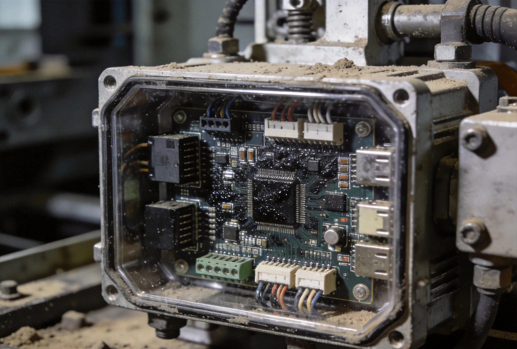
Industrial environments don't forgive design shortcuts. A factory floor PCB operating near heavy machinery experiences vibration levels that would crack a Consumer Electronics board in weeks. Outdoor installations endure temperature swings from freezing winters to scorching summers, sometimes within the same 24-hour period. Chemical processing plants expose electronics to corrosive atmospheres that eat through standard coatings in months.
When I first started designing for industrial applications, I assumed ruggedization meant spending more money on higher-grade components. Over time I learned that the real difference lies in design methodology—how you think about reliability from the earliest stages, and how manufacturing processes either reinforce or undermine your reliability goals. The choices made before a single component is placed determine whether an industrial assembly survives for decades or fails within its first year.
Industrial environments assault electronics from multiple directions simultaneously. Thermal stress comes first—equipment that runs hot during operation and sits cold during shutdown creates cyclic expansion and contraction that fatigues solder joints, delaminates PCB layers, and cracks component terminations over time. The rate of thermal cycling matters as much as the absolute temperature range; equipment that cycles daily stresses materials differently than equipment that runs continuously at elevated temperature.
Vibration represents a different failure mechanism. Rotating machinery, conveyor systems, and hydraulic equipment generate vibration frequencies that couple into nearby electronics. The vibration energy can be relatively low amplitude but persistent, causing fatigue failures in solder joints and mechanical connections over months or years. Higher amplitude shock events—drops, impacts, sudden pressure changes—create immediate mechanical failures that no amount of thermal design can prevent.
Humidity and moisture assault electronics chemically and electrically. High humidity environments cause corrosion of exposed metallization, dendritic growth between closely spaced conductors, and degradation of insulation resistance. When moisture penetrates sealed enclosures, the damage accelerates dramatically. Salt air in coastal or maritime installations creates particularly aggressive corrosion environments that attack aluminum, copper, and even gold-plated surfaces.
Chemical exposure takes many forms. Industrial solvents, cutting fluids, hydraulic fluids, and process chemicals can degrade plastics, rubbers, conformal coatings, and solder mask. Some chemicals penetrate seals and coatings by permeation, meaning no mechanical seal design fully protects against prolonged chemical exposure without proper material selection.
Conformal Coating provides the first line of defense against environmental contamination. The coating forms a thin protective layer over the assembled board, sealing components and traces from moisture, dust, and chemical exposure. Material selection determines whether this protection lasts for years or degrades within months.
Acrylic coatings offer economical protection with good moisture resistance and easy reworkability. They cure quickly, apply with standard spray or dip equipment, and remove cleanly with standard solvents when repair is necessary. The tradeoff is relatively limited chemical resistance—aggressive solvents and some industrial chemicals attack acrylic coatings, limiting their use in chemically harsh environments.
Silicone coatings provide excellent thermal stability and flexibility across wide temperature ranges. They maintain protective properties from -65°C to +200°C, making them suitable for applications where thermal cycling spans extreme ranges. Silicone coatings resist many chemicals better than acrylics and maintain flexibility without cracking during thermal cycling. The main disadvantages are lower abrasion resistance and more challenging rework procedures.
Urethane coatings deliver superior chemical and abrasion resistance for the harshest environments. They withstand exposure to fuels, oils, and industrial solvents that attack other coating types. Urethane comes in both single-component and two-component formulations, with the two-component versions offering improved performance but more complex application requirements. Rework difficulty is higher than acrylic or silicone, requiring specialized removal processes.
Parylene coating stands apart from liquid coatings. Applied through vapor deposition in a vacuum chamber, Parylene penetrates crevices and under components more completely than any spray or dip process can achieve. The resulting coating is extremely thin, uniform, and pinhole-free across the entire board surface. Parylene provides excellent dielectric properties and chemical resistance but at significantly higher cost and with longer application cycles. Repair requires removing the entire coating and re-applying, making Parylene best suited for high-reliability applications where rework frequency is expected to be low.
Standard FR-4 PCB material handles consumer and commercial applications adequately, but industrial environments expose its limitations. The glass transition temperature (Tg) of standard FR-4—typically 130-140°C—becomes relevant when boards operate near heat sources or experience significant self-heating. Above Tg, the material softens and loses mechanical rigidity, potentially causing dimensional instability during assembly reflow or high-temperature operation.
High-Tg FR-4 materials raise the glass transition temperature to 150-180°C, providing improved thermal margin for demanding applications. The tradeoffs include higher material cost and sometimes reduced drill quality compared to standard grades. For boards with controlled impedance requirements, high-Tg materials may require tighter process control to achieve consistent electrical parameters.
Polyimide (PI) and flex materials offer superior thermal performance and flexibility. PI maintains structural integrity at temperatures exceeding 250°C, making it suitable for lead-free assembly processes that require higher reflow temperatures. The flexibility of PI also makes it resistant to thermal cycling fatigue. However, polyimide costs significantly more than FR-4 and requires specialized processing that not all manufacturers handle equally well.
Metal core substrates address Thermal Management challenges directly. By substituting an aluminum or copper core for the standard FR-4 dielectric, thermal conductivity improves by orders of magnitude. Heat from components conducts through the dielectric to the metal core and dissipates into the mounting surface or attached heatsink. Metal core boards cost more and require different assembly approaches, but for high-power-density industrial applications, they often represent the most practical thermal solution.
Vibration survival starts with understanding the frequency content of the vibration environment. Low-frequency, high-amplitude vibration stresses components differently than high-frequency, low-amplitude vibration. Industrial equipment tends toward low-frequency vibration from rotating machinery, while transportation and impact events create higher-frequency shock events. Your mounting approach should address the frequencies actually present in your application.
Shock mounts and vibration isolators interrupt the vibration path between the source and your electronics. Elastomeric mounts attenuate vibration transfer across a range of frequencies, with effectiveness depending on the mount's durometer (hardness) and geometry. Softer mounts provide better isolation but may not survive high-shock environments. Harder mounts handle more extreme conditions but provide less isolation at normal operating frequencies.
Component selection affects vibration susceptibility significantly. Through-hole components with long leads resist vibration better than surface mount parts with small solder pad footprints. When surface mount is necessary for manufacturing efficiency, selecting components with larger termination sizes and higher mass reduces the risk of solder joint fatigue. Components with epoxy underfill or staking compound applied during assembly show dramatically improved vibration survival compared to standard surface mount assembly.
Board reinforcement through stiffening ribs, metal backing plates, or edge connectors distributes vibration-induced stress more evenly across the assembly. A stiff board vibrates less than a flexible one, reducing the cyclic strain on component solder joints. Edge connectors rather than cable connections eliminate the cable fatigue failures that plague vibration-prone designs with wiring harnesses.
Industrial electronics generate heat that must be removed to maintain reliable operation. Components operating above their rated temperature experience accelerated failure mechanisms—capacitors dry out, semiconductors lose blocking voltage capability, solder intermetallics grow, and plastic packages soften. Thermal Management isn't optional in industrial applications; it's a fundamental reliability requirement.
Passive thermal management through conduction, convection, and radiation suffices for many applications. Strategic placement of thermal vias under hot components conducts heat to internal planes or the board surface. Exposed copper areas radiating heat into the surrounding air provide natural convection cooling. Heatsink attachment using Thermal Interface Materials creates efficient conduction paths to mounted heatsinks.
Active cooling through fans or liquid cooling becomes necessary when passive methods can't keep temperatures within ratings. Fans introduce moving parts and reduce mean time between failures, but modern industrial fans designed for continuous operation can provide decades of reliable service. Liquid cooling offers highest heat removal capability but at significant complexity and cost—appropriate only for applications with extreme power dissipation requirements.
Thermal simulation during design catches problems before boards are manufactured. Computational fluid dynamics (CFD) tools model airflow around boards and through enclosures, predicting hot spots and temperature gradients before physical prototypes exist. Investing in simulation early reduces development iterations and produces more reliable thermal designs than trial-and-error prototyping.
The Pcb Assembly rarely operates in isolation—it's mounted inside an enclosure that provides mechanical protection and environmental sealing. The interface between the enclosure and the Pcb Assembly determines whether the overall product survives or fails at the enclosure boundary.
IP (Ingress Protection) ratings define the degree of protection against solid objects and liquids. An IP67 rating indicates complete protection against dust and immersion in water up to 1 meter. Achieving IP67 requires sealing all openings, using appropriate gasket materials, and designing for differential pressure stability. Gasket compression must be controlled—too little compression allows leaks, too much compresses the gasket permanently and degrades seal performance over time.
Breathable membranes solve the differential pressure problem that sealed enclosures create. As temperature changes, air inside a sealed enclosure expands and contracts, creating pressure differentials that stress seals and create leak paths. Breathable membranes allow slow air exchange that equalizes pressure while maintaining particulate and liquid protection.
Conformal Coating and enclosure sealing work together. If the enclosure breathes through a membrane, the coating protects against the humid air that slowly permeates the enclosure. If the coating fails at any point, the enclosure provides backup protection. This defense-in-depth approach is standard practice for industrial electronics where failure consequences are high.
Industrial temperature ratings matter more than automotive or commercial ratings for many factory floor applications. Commercial parts rated 0-70°C can fail rapidly when exposed to -20°C winter warehouse conditions or 50°C equipment ambient temperatures. Industrial parts rated -40°C to +85°C or wider ranges provide the margin necessary for unpredictable industrial thermal environments.
Automotive-qualified components (AEC-Q series) undergo more rigorous testing than standard commercial parts, including temperature cycling, mechanical shock, and humidity exposure. For applications where industrial and automotive requirements overlap—electric vehicles, heavy equipment, transportation systems—AEC-Q qualification provides proven reliability without industrial-specific qualification costs.
Long-lifecycle components reduce the risk of obsolescence disrupting production. When a critical component goes obsolete, the emergency search for alternatives, requalification testing, and potential redesign work can cost more than the price premium for longer-lifecycle parts from the beginning. Specify components with demonstrated availability windows matching your product's expected production life plus a safety margin.
Electrolytic capacitors deserve special attention for long-life applications. Standard electrolytics are among the first components to fail in any electronics product, with failure rates increasing exponentially above rated temperature. When long life is required, specify capacitors with at least 10,000-hour rated life at maximum operating temperature, and derate voltage and ripple current substantially below maximum ratings.
Ruggedized assembly processes differ from standard manufacturing in ways that affect design. Larger pad sizes for components, increased spacing between features, and robust connector choices all depend on manufacturing processes that support the extra clearance requirements.
Paste-in-hole and Wave Soldering processes may be necessary for through-hole components that need stronger solder joints than reflow-only processes can achieve. Boards designed for mixed process assembly require compatible coating materials that withstand both reflow and Wave Soldering temperatures without degradation.
Underfill and staking compound application adds manufacturing steps but dramatically improves vibration and thermal cycling survival. These materials bond components to the board surface, transferring stress from the component package into the board rather than concentrating it at the solder joint. The added process steps increase manufacturing cost but reduce field failure rates in rough environments.
Test access becomes critical in ruggedized assemblies because repair is expensive and difficult. Test points placed for easy probe access reduce debug time and in-circuit test fixture complexity. Boundary scan JTAG testing can reduce dependence on physical test access for complex boards where probe access is limited by dense component placement.
Accelerated life testing validates ruggedization decisions before products enter service. Temperature cycling between temperature extremes, sustained vibration exposure, humidity chambers, and combined stress testing reveal failure modes that design analysis might miss.
Industry standards provide test frameworks that correlate with field reliability. IEC 60068 covers environmental testing for electronic equipment, including temperature cycling, vibration, shock, and humidity tests. MIL-STD-810 provides more aggressive test protocols suitable for defense and aerospace applications. For industrial applications, the appropriate standard depends on the specific environment the product will face.
HALT (Highly Accelerated Life Testing) and HASS (Highly Accelerated Stress Screening) identify design weaknesses rapidly by exposing prototypes to escalating stress levels until failure occurs. The failure point reveals margins against the design limits and guides design improvements before production commitment.
Burn-in testing at elevated temperature for an extended period screens out early-life failures from components or manufacturing defects. Not all failures show up immediately—some require weeks or months of operation before they manifest. Burn-in accelerates this timeline, allowing failures to occur during manufacturing rather than in the field.
Ruggedized Pcb assembly for industrial environments requires systematic attention to environmental stressors from the earliest design stages. Thermal management, Vibration Resistance, conformal coating, sealing, and component selection all contribute to reliable operation in conditions that would destroy standard consumer-grade electronics.
The extra engineering effort and manufacturing cost for ruggedization pays back through reduced field failures, extended product life, and satisfied customers who don't experience the downtime and repair costs that inadequate ruggedization produces. In industrial applications where failure consequences are high—safety systems, process control, infrastructure equipment—the investment in proper ruggedization isn't optional.
Working with manufacturing partners experienced in industrial electronics ensures that your design intentions survive translation into physical products. Ruggedization isn't achieved by specification alone—it requires process control, inspection, and testing that confirm protective measures work as designed throughout production.
The Ultimate Guide to Turnkey PCB Prototyping for Hardware EngineersMay/26/2026
Turnkey PCB Assembly for Flight Control Systems and Navigation<June/22/2026

Best Turnkey PCB Assembly for Consumer & IoT ElectronicsJune/16/2026
The Best Turnkey PCB Assembly Solutions for Startups and SMEsAugust/15/2026
Key Insights on DFM (Design for Manufacturing) in Turnkey ProjectsJuly/26/2026

Cost Breakdown Insights: Where Does Your Money Go in Turnkey PCB Assembly?September/24/2026

Expert Insights on Reducing Supply Chain Risks in Turnkey PCB AssemblyJune/03/2026
5 Common Mistakes to Avoid During Turnkey PCB PrototypingJuly/07/2026