Open Nav

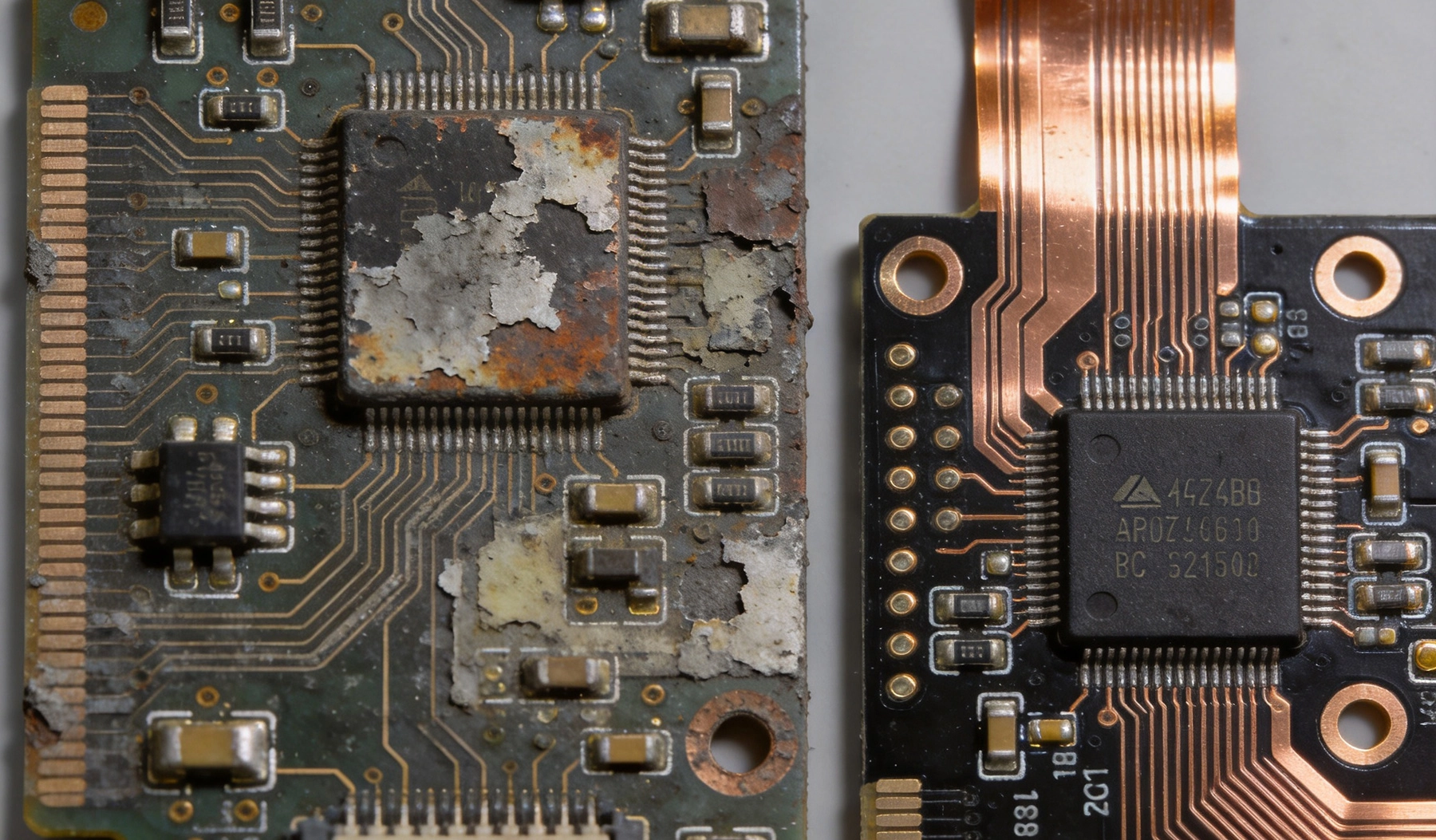
Industrial equipment is expected to operate for decades, not years. A programmable logic controller in a factory automation system, a motor drive in a mining conveyor, a power supply unit in a remote telecommunications shelter — these products are specified for 10, 15, sometimes 20 years of continuous operation. The printed circuit board assemblies inside them must match that lifespan, even as the components mounted on them age, the environment changes, and the Supply Chain shifts underneath the product.
Lifecycle management for industrial PCBA is not a single activity — it is an ongoing discipline that spans product design, component selection, manufacturing qualification, in-field monitoring, and end-of-life planning. Products that consistently meet their longevity targets are not lucky. They are designed and managed that way from the start.
Consumer Electronics operate in controlled environments, are replaced frequently, and are rarely subjected to extreme thermal or vibration stress. Industrial PCBA operates in the opposite conditions: uncontrolled temperatures, high humidity, persistent vibration, chemical exposure, and power quality issues. The consequences of failure are also categorically different — a consumer device failure is an inconvenience; a failure in a factory automation controller or a power distribution system can halt production lines, create safety hazards, and cost tens of thousands of dollars per hour of downtime.
This operational context shapes every decision in the lifecycle of an industrial PCBA product, from the initial design through end-of-life support.
Derating is the practice of operating components below their maximum rated stress levels — electrical, thermal, and mechanical. A capacitor rated for 105°C is specified for 85°C operation. A MOSFET rated for 30A is operated at 15A. A resistor rated for 0.5W is used where it dissipates 0.25W. This is not overengineering — it is the primary engineering tool for extending product life.
The physics of component aging make derating essential. Most failure mechanisms in electronic components — electromigration, dendritic growth, thermal cycling fatigue, moisture ingress — follow Arrhenius-type relationships, where failure rate doubles for every 10°C increase in operating temperature. A component operating at 80% of its rated stress has a significantly lower failure rate over time than one operating at 100%. The exact curves depend on the component type and the stress mode, but the direction is always the same: less stress means longer life.
Industrial PCBA design standards typically specify derating factors for key component categories:
Heat is the primary accelerator of aging in electronic components. Every joule of heat that can be removed from a junction, a winding, or a capacitor extends the component's useful life. For industrial PCBA, thermal design is not just about preventing immediate overheating — it is about ensuring that the steady-state operating temperature over years of continuous operation stays within a range that supports the target lifespan.
A well-designed industrial board accounts for worst-case thermal conditions — not just the typical operating environment. A product deployed in a desert telecom shelter or a tropical mine can experience ambient temperatures of 50°C or higher for extended periods. The thermal design must ensure that even under these worst-case conditions, component junction temperatures remain within derated limits.
Thermal simulation during design, combined with thermocouple measurement of prototype units under worst-case load and ambient conditions, provides the confidence that the thermal design will support the target lifespan in the field.
For safety-critical or high-availability industrial applications, redundancy is a core longevity strategy. Rather than designing a single path for critical functions, the design incorporates parallel paths that can maintain operation if one path fails. This is common in power supply design (N+1 redundancy in power modules), motor control (dual-redundant winding drives), and control systems (redundant communication channels).
Redundancy does not eliminate the need for component reliability — it reduces the consequences of individual component failures by distributing load and providing alternate paths. When combined with condition monitoring (discussed below), redundant systems allow maintenance teams to replace degrading components proactively, before they fail and force a switchover to the backup path.
Not all components with the same datasheet specifications are equal from a longevity standpoint. Component manufacturer quality, process capability, and historical field failure rates vary significantly. Industrial-grade components — specified for extended temperature ranges (-40°C to +85°C or +125°C), longer warranty periods, and more rigorous qualification testing — are designed with longevity in mind in ways that consumer-grade components are not.
When selecting components for long-lifecycle industrial products, look for:
Component obsolescence is one of the most significant lifecycle management challenges in Industrial Electronics. Semiconductors, in particular, have typical product lifecycle phases — introduction, growth, maturity, and discontinuation — that can span 5 to 15 years for industrial-grade parts, significantly shorter than the 20+ year service life expected of the equipment they go into.
When a component is discontinued, the original manufacturer typically offers a last-time-buy window, after which the part is no longer available. A board that was designed around that component faces either a redesign (expensive and time-consuming) or an emergency shortage of the component or the board itself.
Proactive obsolescence management includes:
As components age and original manufacturing sources dry up, the risk of counterfeit components entering the Supply Chain increases. Counterfeit semiconductors — ranging from remarked parts (re-marked to appear as higher-grade or more recent date codes) to fully fraudulent devices — have significantly degraded reliability compared to authentic components and represent a serious risk to long-term product reliability.
Prevention strategies include purchasing only from authorized distributors with traceability to the original manufacturer, implementing incoming inspection programs that include X-ray, decapsulation, and electrical testing for suspect parts, and maintaining strict anti-counterfeit policies in supplier agreements.
Traditional industrial maintenance follows a reactive model — equipment runs until it fails, then it is repaired or replaced. For critical systems, this approach is inadequate because unplanned downtime is extremely costly and a sudden failure can cause cascading damage to other systems or create safety hazards.
The transition to predictive maintenance — monitoring the health of PCBA assemblies in the field and scheduling maintenance before failures occur — requires embedded monitoring capabilities in the product itself. Modern industrial controllers and Power Electronics increasingly incorporate built-in self-test (BIST) functions, health monitoring ICs, and communication interfaces that report operational data to maintenance management systems.
The data that predictive maintenance systems collect and analyze includes:
For Power Electronics modules — motor drives, inverters, power supplies — condition monitoring has advanced significantly in recent years. Online insulation resistance monitoring (IR monitoring) detects the gradual degradation of insulation in motors and transformers before a catastrophic failure occurs. Junction temperature estimation using thermal models — rather than direct thermocouple measurement — allows real-time monitoring of semiconductor health without invasive sensors.
Gate driver health monitoring in IGBT and MOSFET modules can detect early signs of bond-wire fatigue, one of the most common failure mechanisms in power modules. When bond-wire degradation is detected, the module can be scheduled for replacement during a planned maintenance window rather than causing an unplanned outage.
Designing a product for 15 years of field operation cannot wait 15 years for validation. Accelerated life testing (ALT) uses elevated stress levels — thermal, electrical, vibration — to compress time and simulate the aging that occurs over years of normal operation in a matter of weeks or months.
The most common accelerated test methods for industrial PCBA include:
The results of ALT, combined with known acceleration factors for specific failure mechanisms, allow reliability engineers to estimate field failure rates and predict product lifespan with statistical confidence — without waiting for actual field failures to accumulate over years.
The most valuable reliability data comes from actual field failures. A robust field failure analysis program — where every returned board is examined, root cause identified, and findings fed back into the design and qualification process — is the most direct route to improving product longevity over successive generations.
Best-practice field analysis programs include:
No product lasts forever, and industrial PCBA products eventually reach end-of-life — not because they fail, but because the market they serve evolves, the technology becomes obsolete, or the original components are no longer available. Managing this transition gracefully is as much a part of lifecycle management as designing for long life.
An end-of-life plan should be developed early in the product lifecycle — ideally at launch — and revisited annually as the component landscape shifts. Key elements include:
For products that have reached the end of their planned production life but are still deployed in the field, a sustainment engineering approach can extend operational life without a full redesign:
Perhaps the most overlooked aspect of end-of-life planning is documentation. As products mature and original engineering teams move on, the institutional knowledge about a product — design rationale, qualification data, known failure modes, rework procedures — can disappear. Comprehensive technical documentation packages, including design files, qualification reports, test procedures, and field failure analysis records, are essential for maintaining the ability to support a product through its full service life and through any redesign or transition activities.
Lifecycle management for industrial PCBA is a continuous discipline that begins at product concept and continues through end-of-life. The factories, engineering teams, and supply chain organizations that consistently deliver long-life industrial products share a common characteristic: they treat longevity as a design requirement, not as a hope.
Derating for thermal and electrical margin, selecting components with proven longevity track records, implementing predictive maintenance capabilities, planning for component obsolescence years before it arrives, and feeding field failure data back into continuous improvement — these are the practices that separate products with 20-year field track records from those that require constant engineering firefighting.
For companies sourcing industrial PCBA from manufacturing partners, evaluating the partner's lifecycle management practices — their component lifecycle tracking, their reliability testing programs, their field failure analysis capabilities, and their end-of-life planning processes — is as important as evaluating their assembly quality and delivery performance. A product that lasts 20 years is ultimately a better business outcome than one that is cheaper at the unit level but requires repeated costly interventions over the same period.
Derating is the practice of operating electronic components below their maximum rated stress levels — typically using components at 50–80% of their rated current, voltage, power, or temperature. The physics of component aging means that lower stress dramatically reduces failure rates over time. A semiconductor operated at 60% of rated current will typically last two to five times longer than one operated at 100%. Industrial PCBA standards specify derating factors for each component category as a baseline requirement for long-lifecycle products.
Component obsolescence is one of the most significant threats to long-term product continuity. Industrial products are often expected to operate for 15–20 years, but the components used to build them may be discontinued after 5–10 years of production. Managing this requires proactive obsolescence monitoring, strategic buffer stock purchases during last-time-buy windows, second-source component qualification before the original is discontinued, and a redesign capability for scenarios where substitution is not viable. Without a formal obsolescence management program, a single discontinued component can halt production of an entire product line.
Accelerated life testing compresses years of field aging into weeks or months using elevated stress levels. Common methods include High Temperature Operating Life (HTOL) testing at elevated ambient temperatures, thermal cycling between temperature extremes to fatigue solder joints and plated vias, power temperature cycling that applies simultaneous thermal and electrical stress, and Highly Accelerated Life Testing (HALT) that step-stresses products to destruction to identify design margins. Test results are extrapolated to field conditions using established acceleration factor models — particularly the Arrhenius relationship for thermal aging — to estimate field failure rates and product lifespan.
Predictive maintenance for industrial PCBA uses embedded monitoring to track the health of assemblies in the field, allowing maintenance to be scheduled before failures occur rather than reacting to failures after they happen. Monitoring approaches include online measurement of operating temperature profiles, electrical parameter drift detection, insulation resistance monitoring for motor drive systems, and power consumption pattern analysis. When monitored parameters deviate from established baselines, algorithms can predict remaining component life and trigger maintenance actions before a failure causes unplanned downtime.
Counterfeit components — including remarked parts, cloned devices, and fully fraudulent components — are a significant risk for products with long service lives, as the supply of authentic components diminishes over time. Prevention requires purchasing exclusively from authorized distributors with full traceability to the original manufacturer, implementing incoming inspection programs that include visual examination, X-ray analysis of package integrity, decapsulation to verify die markings, and electrical testing against datasheet specifications. Maintaining strict anti-counterfeit clauses in supplier agreements and registering with manufacturer product change notification programs also reduces exposure to counterfeit parts.
Field failure analysis (FFA) is the process of systematically examining returned boards to determine the root cause of each failure. Every returned unit represents an opportunity to learn about actual failure mechanisms in real-world operating conditions — information that accelerated life testing alone cannot fully replicate. A robust FFA program includes non-destructive analysis first, detailed failure classification, trending analysis to identify systematic issues, and formal Corrective and Preventive Action (CAPA) reports that feed lessons learned back into design, component selection, and manufacturing process improvements. Over successive product generations, this feedback loop is the most effective mechanism for improving product longevity.
Turnkey PCB Solutions: Bridging the Gap Between Design and Mass ProductionAugust/06/2026
Best Turnkey PCB Assembly for Industrial & Automation: Built to LastJune/27/2026
Turnkey PCB Assembly for PLCs and Motor Control DrivesAugust/11/2026
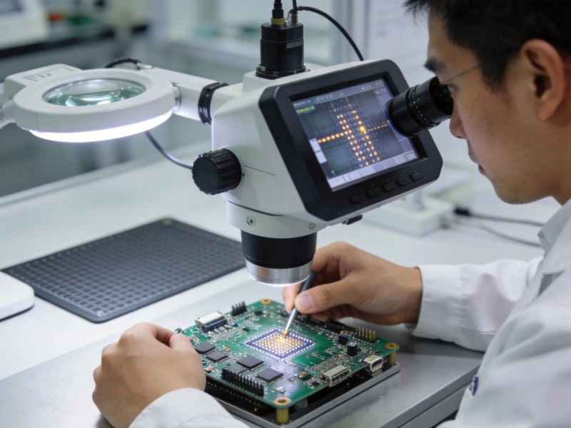
Quality Control Standards in Turnkey SMT Assembly (IPC-A-610 Explained)July/07/2026
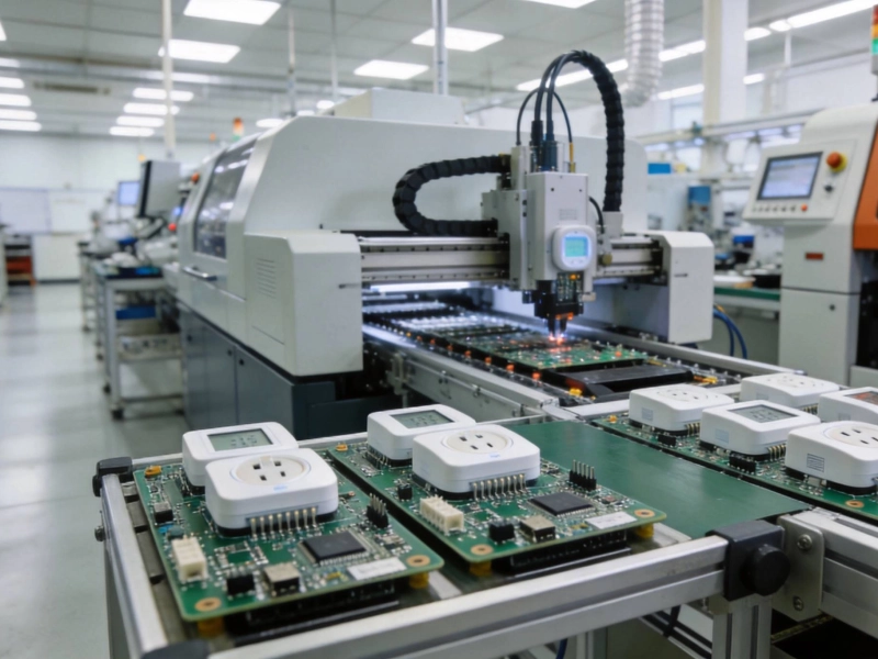
Cost-Effective Turnkey PCB Assembly Strategies for Smart Home DevicesAugust/06/2026
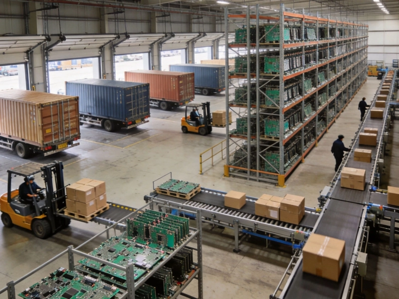
Supply Chain Resilience in High Volume Turnkey PCBA ProjectsJuly/10/2026
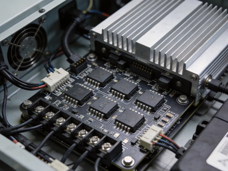
Best Turnkey PCB Assembly for EV Charging Stations and InvertersSeptember/15/2026
Advanced Turnkey SMT Assembly Techniques for High-Density InterconnectsMay/26/2026