
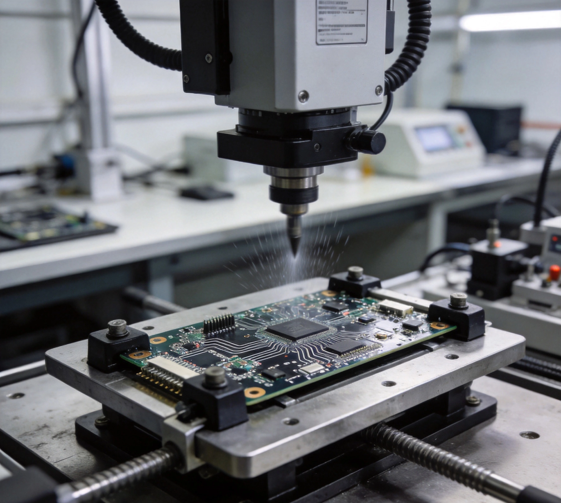
Under the hood of every modern vehicle, electronic control units face relentless mechanical stress. Road surface irregularities transmit constant vibration through the chassis, while engine operation generates rhythmic oscillations at specific frequencies. Add sudden impacts from potholes, speed bumps, and collisions, and automotive PCBs must survive environments far more demanding than typical Consumer Electronics applications.
Meeting these challenges requires deliberate design strategies, specialized materials, and rigorous testing protocols. Automotive Pcb Assembly that fails to address vibration and shock resistance risks premature field failures, warranty claims, and potentially dangerous system malfunctions in safety-critical applications like braking, steering, and airbag deployment.
Automotive vibration originates from multiple sources with distinct frequency signatures. Engine cylinders firing create periodic disturbances, with frequencies corresponding to engine speed and cylinder count. The drivetrain generates harmonics related to gear ratios and rotational speeds. Road surface interaction produces random vibration patterns that vary with vehicle speed, tire condition, and surface type.
Shock events differ fundamentally from continuous vibration. Door slams, trunk closures, and collision impacts generate brief but intense acceleration pulses. These transient events can exceed sustained vibration levels by orders of magnitude, testing different failure mechanisms than fatigue from prolonged oscillation.
Automotive environments combine mechanical stress with temperature extremes that worsen material degradation. A PCB mounted near the engine bay might experience temperatures from -40°C during winter cold starts to +125°C during summer highway driving. These thermal cycles induce differential expansion between materials with different coefficients of thermal expansion, creating internal stresses that compound vibration effects.
Material properties change significantly across this temperature range. Solder joints become more brittle at cold temperatures while polymer materials soften at high temperatures. Vibration Resistance that appears adequate at room temperature may prove insufficient at temperature extremes that vehicles routinely experience.
The Automotive Electronics industry relies on standards from multiple organizations to define Vibration Resistance requirements. IPC-A-610 establishes general acceptability criteria for electronic assemblies, but automotive applications typically require additional verification beyond Consumer Electronics standards.
AEC-Q100 addresses integrated circuits, while AEC-Q200 covers passive components. Both standards include stress test requirements for vibration and thermal cycling. These qualifications verify that components can survive automotive environments before they enter assembly supply chains, though assembly-level verification remains necessary for complete boards.
Major automotive manufacturers publish their own specifications that exceed baseline industry standards. Ford, GM, Toyota, and other OEMs each have document systems defining acceptable vibration levels, test methodologies, and documentation requirements. These specifications often reference vibration profiles derived from actual vehicle testing rather than generic laboratory simulations.
Compliance with OEM specifications requires understanding which standards apply to your target application. Powertrain controllers face different requirements than infotainment systems, and safety-critical brake controllers demand testing rigor exceeding body electronics specifications. Matching requirements to application ensures adequate testing without unnecessary over-specification.
Thicker boards resist deflection more effectively than thin boards of identical construction. Standard consumer electronics PCBs typically use 0.8mm to 1.6mm thickness, while automotive applications commonly specify 1.6mm to 3.2mm boards for vibration-critical applications. This increased stiffness reduces dynamic response to excitation frequencies.
The tradeoff involves weight and cost. Heavier boards increase vehicle weight and material expenses. Careful analysis of expected vibration spectra helps optimize thickness for specific applications rather than over-engineering universally thick boards throughout the vehicle.
Strategic component placement significantly affects vibration survival. Heavy components create larger inertial masses that strain solder joints when the board deflects. Placing heavy parts near mounting points where board motion is minimal reduces stress on critical connections. Avoiding placement near board edges or unsupported spans where deflection amplitudes peak improves reliability.
Component orientation relative to likely vibration axes matters for packages with asymmetric lead configurations. Aligning component long axes perpendicular to expected vibration directions minimizes stress on vulnerable solder joints. This orientation optimization requires understanding typical vibration spectra for the specific mounting location in the vehicle.
Potting compounds and underfill materials mechanically reinforce component-to-board connections. These materials surround solder joints, transferring stress from compliant solder to the more robust compound, reducing fatigue in the connection interface. Underfill proves particularly valuable for chip-scale packages and ball grid arrays where solder joint area is small relative to component mass.
Material selection balances mechanical protection against thermal performance. Some potting compounds restrict heat flow from components, potentially causing thermal throttling or reduced lifespan. Thermal analysis verifies that added protection doesn't compromise operating temperature limits.
For extreme vibration environments, flexible circuit sections between rigid board areas absorb mechanical energy that would otherwise stress solder joints. Rigid-flex assemblies allow controlled compliance where vibration threatens, with stiff sections for components requiring stable mounting and flexible sections that deform to absorb shock energy.
These constructions add design complexity and manufacturing cost, making them appropriate only for applications where vibration levels exceed what rigid boards can reliably survive. Engine control units and sensors mounted directly on engines often use rigid-flex specifically for vibration survivability.
How PCBs attach to vehicle structures fundamentally affects vibration exposure. Direct mounting to rigid chassis transmits maximum vibration, while standoff mounts with isolating bushings attenuate vibration before it reaches the board. This isolation works by introducing compliance between vibration source and sensitive electronics.
Isolation effectiveness depends on matching mount stiffness to expected frequencies. Too soft, and the assembly resonates at frequencies that amplify rather than attenuate vibration. Too stiff, and isolation benefits disappear. Engineering analysis of the complete system—vehicle structure, mount properties, and board dynamics—optimizes mount selection.
Board edges experience high stress concentrations during vibration. Metal support rails or continuous edge clamping distribute mounting forces across larger areas, reducing local stress peaks. These mechanical features also provide EMC shielding benefits in many automotive applications, creating synergy between mechanical and electrical requirements.
Chassis grounds often connect through mounting hardware, requiring careful design to ensure reliable electrical contact under vibration. Separate mechanical and electrical ground connections prevent intermittent electrical issues from vibration-induced micromotion in shared mounting points.
Connectors create mechanical discontinuities where cable movement transmits stress to board connections. Connector strain relief directs cable forces away from solder joints, often through connector housings that clamp cables before they reach board terminations. This protection proves essential for any cable-connected assembly.
Board-mount connectors without adequate retention can lift from pads under vibration loads. Screw-down retention, clips, or adhesive mounting supplements solder strength for vibration-critical connector applications. Verifying retention strength through pull-test and vibration testing confirms adequate protection.
Glass transition temperature (Tg) specifies the temperature where laminate materials transition from rigid to rubbery state. Standard FR-4 materials with Tg around 130°C may approach this limit in under-hood applications where temperatures approach 125°C. High-Tg materials with Tg above 150°C or 170°C provide greater margin against softening that compromises mechanical integrity.
Beyond Tg, thermal cycling performance depends on coefficient of thermal expansion (CTE) matching between laminate, copper, and components. Low-CTE laminates reduce differential expansion stresses that fatigue solder joints over thermal cycles. These materials cost more than standard grades but improve reliability in demanding applications.
Automotive qualification typically requires moisture sensitivity level (MSL) management to prevent delamination during assembly reflow profiles. Beyond assembly, field exposure to humidity and thermal cycling creates conditions where moisture absorption can cause popcorn cracking. Proper storage, handling, and bake-out procedures prevent these failures regardless of board materials.
Conformal coatings provide moisture barriers that protect both the board and solder joints. These polymer coatings also add mechanical support that reduces vibration-induced flexure. Material selection considers temperature rating, flexibility at cold temperatures, and application method suitability.
Most automotive vibration specifications use random vibration profiles rather than sinusoidal sweeps. Random vibration better represents real-world conditions where multiple vibration sources combine into complex spectra without discrete frequencies. Test specifications define acceleration spectral density (ASD) levels across frequency ranges, typically from 20Hz to 500Hz or higher.
Duration depends on qualification intent. Short duration tests might simulate single lifetime exposure, while longer accelerated tests compress multiple vehicle lifetimes into test duration. Correlation between test acceleration levels and real-world exposure enables lifetime compression without unrealistic acceleration that might trigger unrelated failure modes.
Shock testing applies half-sine or sawtooth acceleration pulses of specified amplitude and duration. Automotive shock requirements typically specify 30g to 50g pulses lasting 6ms to 11ms, representing severe impacts. Testing in multiple axes—usually three orthogonal directions—verifies performance regardless of impact orientation.
Functional monitoring during shock testing detects intermittent failures that static post-shock inspection might miss. Boards that continue operating through shock events without error demonstrate adequate margin against real-world impacts.
After vibration or shock testing, destructive analysis reveals failure mechanisms that electrical testing might not detect. Cross-sectioning of solder joints shows crack propagation patterns. Dye penetrant inspection reveals cracks in plated through-holes or component bodies. Acoustic microscopy detects delamination between layers.
These analytical techniques identify weaknesses before field failures occur. When analysis reveals inadequate margin, design improvements address specific failure mechanisms rather than applying generic solutions.
Modern Pcb Design increasingly uses finite element analysis (FEA) to predict vibration response before physical testing. FEA models board geometry, material properties, and mounting configuration to calculate natural frequencies, mode shapes, and stress distributions under applied loads. This predictive capability identifies resonance vulnerabilities early in development.
Coupled multiphysics analysis accounts for interactions between thermal and mechanical effects. High temperatures reduce material stiffness, changing vibration response. FEA that captures these interactions provides more accurate predictions than thermal and mechanical analyses performed independently.
Automotive reliability targets typically specify failure rates in parts per million (PPM) or mean time between failures (MTBF). These metrics derive from accelerated life testing that compresses years of field exposure into laboratory duration. Statistical analysis of test results projects field performance with quantifiable confidence levels.
Different vehicle systems have different reliability requirements. Infotainment failures inconvenience passengers, while airbag control failures risk fatalities. Reliability targets must match application criticality, with safety-critical systems receiving more conservative design margins and extensive validation.
Automotive Quality Management System requirements (Iatf 16949) mandate demonstrated process capability for critical characteristics. Assembly processes must achieve Cpk values of 1.33 or higher for dimensions or parameters affecting vibration resistance. This statistical evidence proves that manufacturing processes produce consistent results meeting design intent.
Process capability documentation accompanies every production lot. Traceability from assembly records through incoming materials enables root cause analysis when field issues emerge. This traceability infrastructure represents significant investment but proves invaluable when failures require investigation.
The Production Part Approval Process (PPAP) formalizes automotive Supplier Qualification. PPAP submission includes design records, engineering change documentation, process flow diagrams, Process Failure Mode and Effects Analysis (PFMEA), control plans, and measurement system analysis. These documents collectively demonstrate understanding and control of factors affecting vibration resistance.
PPAP levels vary from submission to production run verification. Higher PPAP levels demand more extensive documentation and sample quantities. Understanding customer PPAP requirements ensures timely approval without unnecessary documentation burden.
Cycling stress from vibration gradually propagates cracks through solder joints. This fatigue damage accumulates over vehicle lifetime, eventually causing electrical opens or intermittent connections. Prevention strategies include reducing stress amplitudes through board stiffening, adding mechanical support through underfill or staking, and using fatigue-resistant solder alloys.
Lead-free solders like SAC305 (tin-silver-copper) offer environmental benefits but exhibit faster fatigue progression than traditional tin-lead solders. This trade-off requires careful consideration for high-vibration applications where replacement intervals are long and reliability expectations are high.
Via barrel cracking occurs when vibration stress concentrates at the interface between rigid vias and flexible board material. This failure mode particularly affects boards where vias connect to surface features experiencing high stress concentration. Back-drilling to remove non-functional vias and increasing via barrel thickness both improve survivability.
Blind and buried vias eliminate surface termination points where stress concentrations peak. While these via technologies cost more, they eliminate surface reliability concerns that through-hole vias cannot fully address.
Ceramic components and packages with brittle bodies can crack under vibration stress. This failure mode proves particularly insidious because cracks may not cause immediate electrical failure, instead creating intermittent problems that are difficult to diagnose. X-ray and acoustic inspection detect cracks that visual examination misses.
Reducing board deflection through stiffening, adding compliant mounting, and selecting components with proven vibration survivability all contribute to preventing this failure mode. Component qualification testing should include vibration exposure before design approval.
Most automotive vibration energy concentrates below 500Hz, with significant content from 20Hz to 200Hz. Engine-related vibration typically falls in 50Hz to 150Hz range, while road-induced vibration often peaks between 100Hz and 300Hz. Understanding the specific mounting location's vibration spectrum guides design optimization.
High temperatures reduce material stiffness and strength while differential expansion creates internal stresses. Cold temperatures embrittle solder joints and increase crack propagation rates. Thermal cycling amplifies vibration damage by combining fatigue from mechanical stress with material property degradation from temperature exposure.
Under-hood applications typically use 2.0mm to 3.2mm board thickness for adequate stiffness. Thinner boards risk excessive flexure that fatigues solder joints over vehicle lifetime. Specific requirements depend on mounting configuration, component masses, and expected vibration levels at the specific installation location.
Vibration testing uses electrodynamic shakers that accelerate test articles according to specified profiles. Boards mount to shaker fixtures using production-equivalent mounting methods. Testing spans multiple axes with duration representing expected lifetime exposure. Functional monitoring detects intermittent failures during testing.
Acrylic, urethane, and silicone coatings all provide mechanical support that reduces vibration-induced flexure. Acrylic coatings offer fast curing and reworkability. Urethane provides excellent chemical and moisture resistance. Silicone coatings maintain flexibility at cold temperatures, important for applications experiencing severe thermal cycling.
Automotive specifications typically exceed consumer requirements significantly. Vibration levels may be 5-10 times higher, temperature ranges are wider, and qualification testing is more extensive. Lifetime expectations are longer—10 to 15 years for automotive versus 3-5 years for consumer products. Documentation and traceability requirements are also substantially more rigorous.
Vibration and shock resistance in automotive Pcb Assembly demands systematic attention to design, materials, mounting, and testing throughout development. The consequences of inadequate protection extend beyond component failures to potential safety incidents that put vehicle occupants at risk. This responsibility motivates the extensive qualification requirements that Automotive Electronics must satisfy.
Successful automotive Pcb Design integrates mechanical, thermal, and electrical engineering considerations from initial concept through production validation. Simulation tools enable optimization before expensive prototypes, while rigorous testing verifies predictions and catches issues that analysis might miss. This combined approach builds confidence that designs will survive automotive environments throughout vehicle lifetime.
As vehicles incorporate increasing electronic content for autonomy, electrification, and connectivity, vibration reliability becomes even more critical. Systems that were mechanically isolated in traditional architectures now communicate through networks while sharing mounting structures with high-voltage battery systems and electric drive motors. Meeting these challenges requires continued evolution of vibration resistance strategies while maintaining the quality levels that automotive customers expect.
Best Turnkey PCB Assembly for Electric Vehicle Control UnitsSeptember/16/2026
Best Turnkey PCB Assembly for Automotive & EV Systems: Meeting IATF 16949June/18/2026

The Role of Turnkey PCB Assembly in Advanced Driver Assistance Systems (ADAS)July/17/2026
Comprehensive Turnkey PCB Solutions for Complex Electronic SystemsJuly/14/2026
Ruggedized PCB Assembly for Harsh Industrial EnvironmentsJuly/20/2026

Turnkey PCB Assembly Insights: 2026 Industry Trends and Market AnalysisMay/26/2026
How to Verify Material Quality in Turnkey PCB ManufacturingJuly/30/2026
The Trade-offs Between Speed and Cost in Rapid Turnkey PCBAJuly/13/2026