Open Nav


The first board off the line tells you more than any other. A successful first article means your design, your fabrication data, and your assembly instructions have all aligned correctly. A problem caught at first article is a problem fixed at minimal cost. The same problem found after 500 boards are built is a different story entirely — one that involves rework, schedule delays, and difficult conversations with your customer.
In turnkey Pcb Prototyping, where the fabrication, component sourcing, and assembly all happen under one roof, first-article inspection is the quality gate that validates the entire process chain. This article covers what to inspect, how to document it, and how to work with your turnkey partner to make first-article inspection a meaningful verification rather than a paperwork exercise.
First-article inspection, often abbreviated FAI, is the formal verification that the first production unit matches the design intent across all specified parameters. It is not a Design Review — that happens earlier. It is not a functional test — that happens later. FAI is the confirmation that the manufacturing process has correctly interpreted and executed the design documentation.
In a turnkey context, FAI covers three domains: fabrication verification, assembly verification, and documentation verification. Each domain has specific inspection points. Skipping any of them defeats the purpose of FAI and increases the risk that defects propagate into production volume.
The bare board is the foundation. If the board is wrong, nothing built on it can be right. Fabrication FAI should cover the following parameters explicitly.
Request a cross-section of the first article. This shows the actual layer thicknesses, dielectric spacing, and plating quality. Compare the cross-section against your stack-up drawing. Verify that copper weights match specification, prepreg thicknesses are within tolerance, and overall board thickness meets your requirement.
For impedance-controlled boards, the cross-section is especially important. It confirms that the dielectric thickness under controlled-impedance traces matches the design assumption. Impedance testing on a coupon tells you the electrical result; the cross-section tells you whether the stack-up construction explains that result.
Verify that drill sizes match the fabrication drawing. For plated through-holes, confirm that finished hole size is within tolerance after plating. For non-plated holes, confirm drill diameter and position accuracy. If your design includes press-fit connector holes, these require particular attention — hole size tolerance for press-fit applications is typically tighter than for standard through-hole components.
Check via plating quality in the cross-section. Look for voids, cracks, or inadequate plating thickness in via barrels. These defects are not visible from the surface and will cause reliability problems later if not caught.
Verify solder mask registration and coverage. Mask misregistration can encroach on pads or expose traces that should be covered. Check that mask definition around fine-pitch pads is clean and consistent.
Confirm surface finish type and thickness. For ENIG, verify nickel thickness under the gold to prevent black-pad issues. For hard gold on edge connectors, measure gold thickness against your contact requirements. Document these measurements in the FAI report.
Measure board outline against the fabrication drawing. For boards that must fit into enclosures, verify that critical dimensions are within tolerance. Use a coordinate measuring machine or optical measurement system for accurate dimensional verification.
Check bow and twist against IPC limits or your specified requirements. Excessive board warpage affects assembly yield, especially for large BGA components.
Assembly FAI verifies that components are correctly placed, soldered, and oriented. It is the final confirmation that the build intent has been realized.
Verify that all components are present and correctly identified. This includes checking part numbers against the bill of materials, confirming package types match the footprint, and verifying that component values and ratings are correct for the design intent.
Check component orientation for polarized parts. Diodes, tantalum capacitors, ICs, and connectors all have specific orientation requirements. A reversed diode or backwards connector is a common assembly error that FAI should catch.
Verify placement location against the assembly drawing. For fine-pitch components, check alignment to pads. Misalignment can cause open joints or bridges even if the component is nominally placed in the correct location.
Inspect solder joints against IPC-A-610 criteria. Look for proper fillet formation, adequate wetting, and absence of defects such as bridging, cold joints, or insufficient solder. For lead-free solder joints, apply the appropriate acceptance criteria for the alloy used.
For BGA components, X-ray inspection is necessary to verify joint quality underneath the component. X-ray shows bridges, voids, and missing balls that are not visible from the surface. Request X-ray images of BGAs as part of the FAI documentation.
Verify that the board meets ionic cleanliness requirements if specified. Flux residues can cause leakage currents and corrosion over time. Ionograph or similar testing quantifies cleanliness.
If Conformal Coating is applied, verify coverage thickness and absence of bubbles or missed areas. Coating defects affect moisture resistance and long-term reliability.
FAI is not complete without documentation. The inspection report should provide objective evidence that each verification point has been checked and found acceptable.
A comprehensive FAI report contains: cross-section photographs with measurements, drill and hole measurement data, impedance test results (for controlled-impedance boards), surface finish thickness measurements, dimensional measurement data, component placement verification photos or data, solder joint inspection results, X-ray images of BGAs, and cleanliness test results if applicable.
Each measurement should include the nominal value, the measured value, and the tolerance range. This format makes it easy to confirm compliance and identify any marginal conditions.
For turnkey builds, traceability matters. Request date codes and lot codes for critical components. Confirm that the components used match the approved vendor list. This information supports root cause analysis if problems arise later and provides evidence for regulatory or customer audits.
The effectiveness of FAI depends not just on what is inspected but on how the process is managed. These practices improve the odds that FAI adds real value.
Do not assume your turnkey partner knows what you want inspected. Specify FAI requirements in the quote package or purchase order. List the inspection points, the acceptance criteria, and the documentation you require. This avoids ambiguity and ensures the partner allocates appropriate time and resources for FAI.
In some schedules, pressure to ship drives corners to be cut. FAI is not a corner. Request FAI data before authorizing production release. Review the data yourself rather than delegating approval to a purchasing manager who may not understand the technical significance. A day spent reviewing FAI data is cheaper than a month spent managing a field failure.
If FAI reveals issues, document them clearly and work with your partner to resolve them before production. Do not accept verbal assurances that problems will be fixed — get updated inspection data that confirms the correction. This discipline protects both parties and prevents problems from recurring.
FAI data is valuable beyond the immediate build. If you see consistent placement issues with a particular component package, consider whether the footprint design can be improved. If impedance measurements consistently run at one edge of the tolerance window, consider adjusting trace width or stack-up to center the result. FAI data informs continuous improvement if you take the time to analyze it.
Experience from hundreds of prototype builds shows a few recurring patterns that undermine FAI effectiveness:
Skipping cross-section verification. Cross-section is the most informative single inspection for multilayer boards. It shows what is actually inside the board. Skipping it to save cost or time removes critical visibility.
Accepting FAI data without review. The value of FAI is in the review, not just in the data collection. If you do not examine the measurements and compare them to your design intent, you are trusting rather than verifying.
Not specifying BGA X-ray requirements. BGA joint quality cannot be verified visually. If your board has BGAs and you do not request X-ray, you are not inspecting those joints. X-ray should be standard FAI content for any BGA component.
Rushing FAI to meet schedule. Schedule pressure is real, but skipping FAI steps does not save time — it shifts the time cost to problem resolution later. If schedule does not allow proper FAI, the schedule is wrong.
Finding problems at FAI is a success, not a failure. The point of FAI is to catch issues before they become expensive. When FAI reveals problems, respond constructively.
First, document the issue precisely. What is the defect, where is it located, and what is the deviation from specification? Good documentation supports effective communication with your turnkey partner.
Second, work with your partner to identify root cause. Is it a design issue, a fabrication issue, or an assembly issue? The correction depends on where the problem originated. A design issue may require a footprint change. A fabrication issue may require process adjustment on the manufacturer's side. An assembly issue may require improved machine setup or operator training.
Third, verify the correction. Do not assume the problem is fixed because someone said so. Request updated FAI data showing that the issue is resolved and the board now meets specification. This closes the loop and provides documented evidence of compliance.
One of the advantages of turnkey Pcb Prototyping is that fabrication, component sourcing, and assembly all happen under one roof. This consolidation makes FAI more efficient because the same organization controls all the process steps. When issues arise, there is no finger-pointing between separate fabrication and assembly vendors — the turnkey partner owns the complete result.
That advantage is only realized if FAI is actually performed and taken seriously. A turnkey provider that skips FAI or provides superficial inspection reports is not delivering the quality management value that turnkey is supposed to provide. When evaluating turnkey partners, ask specifically about their FAI process, what they inspect, how they document it, and how they handle problems when found. The answers reveal whether their quality program is robust or just window dressing.
Industry standard is to inspect one board from the first production panel. For critical applications or high-value boards, inspecting multiple boards provides greater confidence. The key is that FAI applies to the first articles from the production run, not to pre-production samples that may have been built on different equipment or process settings.
The customer is responsible for reviewing FAI data and approving production release. The turnkey provider is responsible for performing the inspection and providing accurate data. Delegating review to purchasing or administrative staff who do not understand the technical requirements undermines FAI effectiveness. Someone with engineering knowledge of the design should review the data.
If FAI finds a fabrication defect in an assembled board, the decision depends on the severity and location of the defect. Minor cosmetic issues may be acceptable. Structural or electrical defects typically require the board to be scrapped and a replacement built with corrected process. The cost of a populated board with a fabrication defect is a strong argument for inspecting bare boards before assembly in high-risk designs.
Typical FAI turnaround is one to three days after boards are built, depending on the complexity of inspection requirements. Cross-section preparation takes time. Impedance testing and measurement data collection require scheduling. Rushing FAI adds risk. Build FAI time into your project schedule rather than treating it as an afterthought.
FAI is required for the first build of a new design or after a significant process change. For repeat builds of the same design on the same process, FAI may not be required for every lot if the process is stable and controlled. However, many customers request periodic FAI for ongoing production to verify process consistency over time.
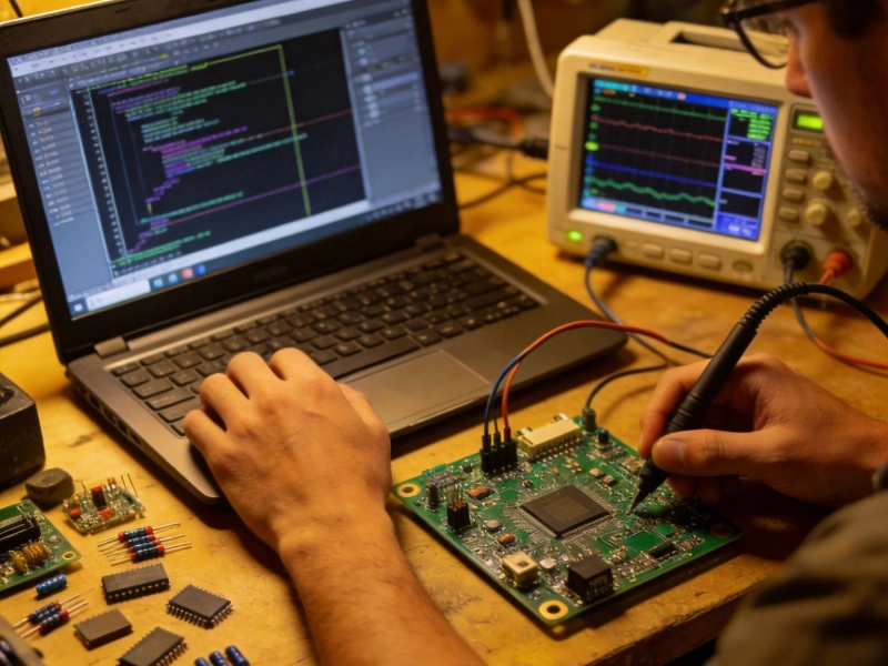
5 Common Mistakes to Avoid During Turnkey PCB PrototypingJuly/07/2026

How Turnkey PCB Prototyping Reduces Development Cycles by 40%June/05/2026

Supply Chain Resilience in High Volume Turnkey PCBA ProjectsJuly/10/2026

Rapid Turnkey PCBA: How to Get Your Electronics Built in Days, Not WeeksJune/15/2026
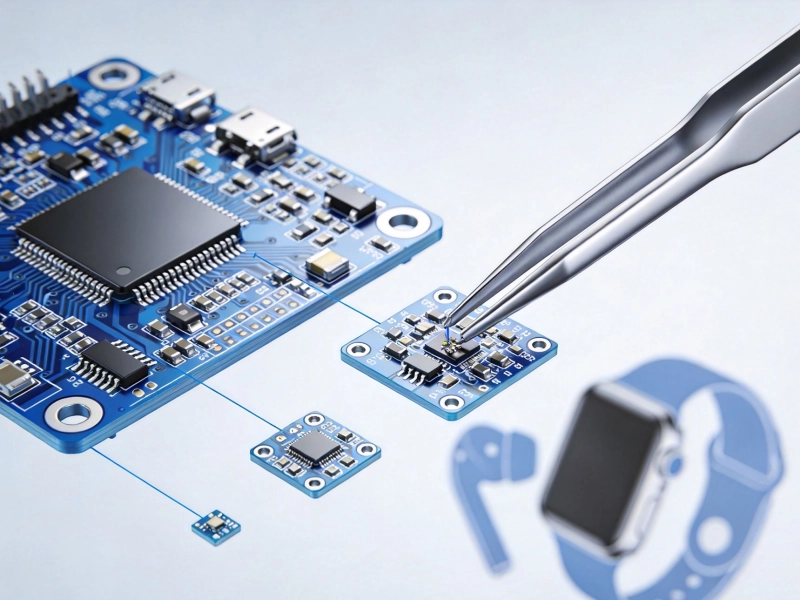
Miniaturization Challenges in Turnkey PCB Assembly for WearablesJuly/15/2026
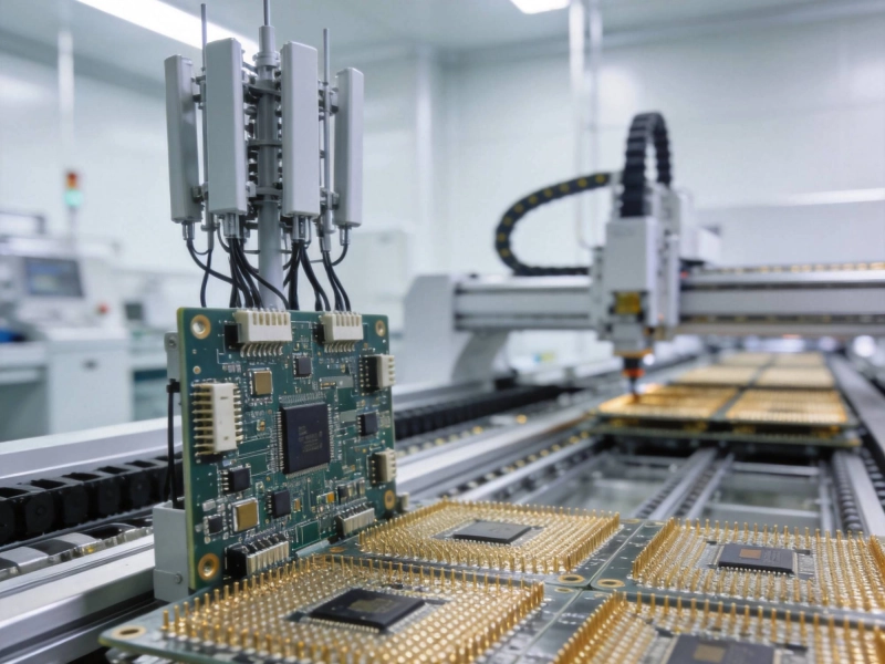
Best Turnkey PCB Assembly for Telecom 5G Infrastructure and Base StationsJune/26/2026
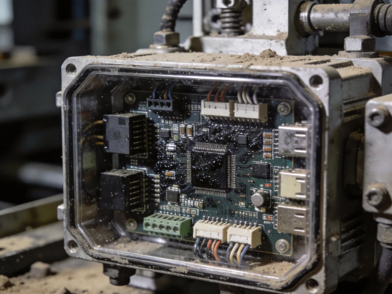
Ruggedized PCB Assembly for Harsh Industrial EnvironmentsJuly/20/2026

Comprehensive Turnkey PCB Solutions for Complex Electronic SystemsJuly/14/2026