
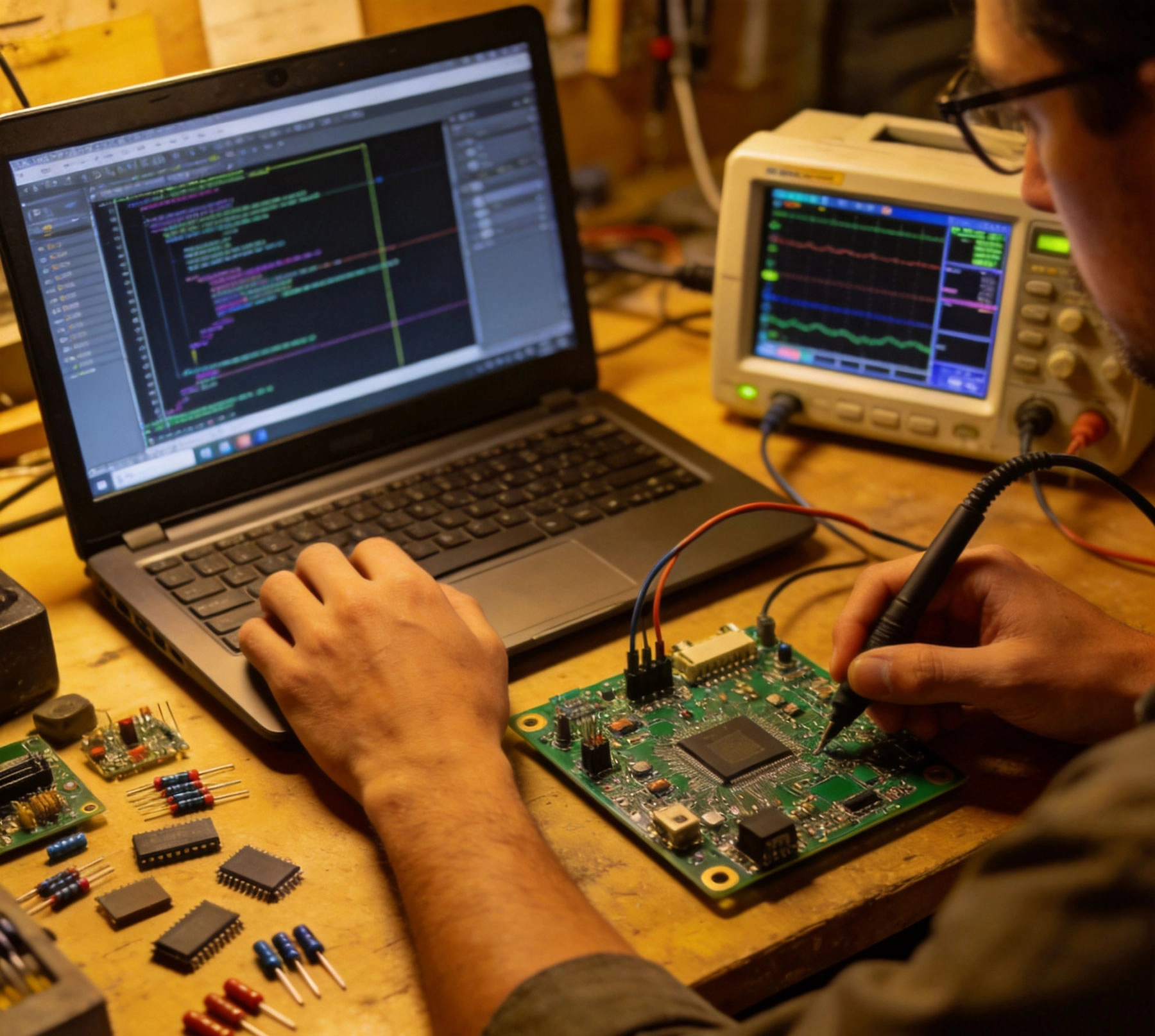
Turnkey Pcb Prototyping has transformed how hardware teams bring electronic products to life. Instead of juggling multiple suppliers—fabrication house here, assembly shop there, component distributor somewhere else—you hand a single provider your design files and receive fully assembled boards ready for testing. The efficiency appeal is obvious. The execution reality often disappoints. Teams routinely experience prototype delays, cost overruns, and board quality that falls short of expectations, all because of avoidable mistakes that seem harmless in isolation but compound into project-disrupting problems.
Having worked with dozens of engineering teams navigating the turnkey prototype process, I've catalogued the recurring patterns that cause the most trouble. These five mistakes appear with such regularity that they merit explicit attention before you submit your next turnkey order. Avoid them, and your prototype experience will be smoother, faster, and considerably less frustrating.
The most common turnkey prototype failure isn't a manufacturing problem—it's a documentation problem. When engineering teams rush to submit orders, they frequently send files that are incomplete, internally inconsistent, or missing critical information that the manufacturer needs to build their boards correctly.
Gerber Files represent the universal language of PCB Fabrication, yet they remain a frequent source of problems. Designers sometimes submit Gerber Files that don't include all required layers—the paste layer might be missing, or the board outline file might reference an outdated revision. Drill files frequently contain inconsistencies: the drill hit count doesn't match what the manufacturer expects, or plated and non-plated holes aren't properly distinguished. These aren't exotic edge cases—they happen constantly in normal prototype workflows.
Assembly drawings cause separate categories of problems. Your manufacturer needs to know which components go where, but a surprising number of turnkey orders arrive with incomplete or contradictory assembly instructions. Silkscreen markings might conflict with the bill of materials. Polarized component orientations might be indicated inconsistently between the drawing and the BOM. Pin 1 indicators might be missing for packages where orientation matters.
The fix is straightforward: implement a design file checklist before every turnkey submission. Verify that all Gerber layers are present and reference the correct board outline. Confirm that the drill file is complete and properly formatted. Cross-check the BOM against the assembly drawing, ensuring that every component on the board appears in the BOM with correct package types and orientations. This checklist takes fifteen minutes to run but prevents days of delay and rework.
Better yet, validate your design files against manufacturer design rules before submission. Most turnkey providers offer free Dfm review services that catch exactly these kinds of problems. Using that service isn't a sign of amateur design—it's a sign of professional Project Management. Teams that consistently get clean prototypes build Dfm review into their standard workflow as a gate before every turnkey order.
Turnkey prototyping promises convenience: you send your design, the manufacturer sources all components, and you receive assembled boards. This convenience masks a complexity that trips up engineering teams constantly—components go out of stock, substitutes become necessary, and design assumptions built around specific parts suddenly require revision.
The scenario plays out with frustrating predictability. Your design specifies an LT1767EMS op-amp from Linear Technology. The turnkey quote looks great. Then component procurement begins, and Linear Technology's distributor is out of stock with an eight-week lead time. Your manufacturer calls asking for approval to substitute an alternative part. The pinout matches, so you approve it. Then you discover during testing that the substitute has different input bias currents that push your front-end offset voltage outside acceptable range. Now you're debugging a problem that exists only because a component substitute changed your circuit behavior.
This pattern repeats across virtually every component category. Passives with tight tolerance requirements get substituted with wider-tolerance alternatives. MLCC capacitors with specific voltage ratings get replaced with equivalents that fail your derating requirement. Connectors with specific keying get substituted with alternatives that physically fit but require redesign of your enclosure. Each substitute seems minor in isolation; together, they can destroy your prototype's fidelity to your intended design.
Prevent component surprises by verifying availability before submitting your turnkey order. Check distributor stock levels for every active component in your design. Identify any components with stock below your immediate needs and source those components yourself before ordering. Specify acceptable substitutes in your purchase order, noting which alternatives are acceptable and which parameters cannot change without your explicit approval. The extra hour spent on availability research saves days of delay and debugging when your prototype arrives.
When substitutions prove unavoidable, get detailed change documentation from your manufacturer. Understand exactly what changed, why, and what electrical or mechanical implications might follow. Don't approve substitutions on faith—review datasheets and assess impact before approving any change to your intended design.
Pcb Design and Pcb Manufacturing are distinct disciplines, and the gap between them creates problems that are entirely preventable. A design that looks perfect in your ECAD tool may violate manufacturing constraints that will either increase your prototype cost dramatically or require redesign before fabrication can proceed.
Trace widths present the most frequent manufacturing friction. Your ECAD design rules might specify 4-mil traces for high-density routing, which works fine in simulation but exceeds the capability of many prototype manufacturers who can't reliably produce traces below 5 or 6 mils. When the fabricator flags this problem, you're looking at layout revisions before your prototype can proceed.
Annular ring violations appear constantly in prototype designs. Vias placed with tight clearance to nearby pads may have insufficient annular ring after manufacturing registration tolerance accumulates. Your design might look fine in the tool but violates IPC annular ring minimums in practice. The fabricator either builds boards that may fail at solder joints or holds the order pending design clarification.
Via sizes create similar problems. Your design might specify 6-mil vias throughout, which is achievable for some manufacturers but not others. A manufacturer whose standard process produces 10-mil vias can't magically manufacture your 6-mil design without special processes and premium pricing. Without DFM review, you discover this mismatch only when you receive a revised quote or quality problems in your prototype.
Pad size and spacing for surface mount components affect manufacturing yield significantly. Packages with fine pitch—0.4mm BGA, 0.5mm QFN—require manufacturing tolerances that prototype shops sometimes can't achieve consistently. Your design may be theoretically producible but practically questionable without manufacturing process qualification.
The solution is straightforward: submit your design for DFM review before finalizing your turnkey order. Professional turnkey manufacturers offer this service because they've learned that early problem identification prevents expensive delays. The review catches design rule violations, identifies manufacturability concerns, and recommends changes that don't affect electrical performance but improve producibility. Accepting this feedback isn't weakness—it's the fastest path to a successful prototype.
Budget time for design revisions when you submit your order. The discovery that your board needs layout changes after your prototype timeline has already committed is far more disruptive than building revision time into your schedule from the beginning.
Turnkey prototyping involves a surprising amount of communication that engineering teams often underestimate. The manufacturer needs information, asks questions, and requests approvals throughout the process. Teams that haven't planned for this communication discover that their prototype timeline depends on responses they're not prepared to provide.
Component substitution requests represent the most common communication bottleneck. When a component goes out of stock, the manufacturer needs approval quickly—production lines can't wait while engineers deliberates for days. Teams that don't have pre-approved substitute lists or established decision-making processes create delays that extend their prototype timeline unnecessarily.
DFM feedback requires engineering assessment and approval before manufacturing can proceed. When a fabricator identifies a potential problem, someone with design authority needs to evaluate the concern and provide direction. If that person is unavailable, waiting for their response delays everything downstream.
Quality questions arise during assembly that require design context. A component placement concern, a solder joint quality judgment, a test point accessibility issue—each requires someone who understands the design intent to provide guidance. Without a designated contact who can make decisions quickly, communication bottlenecks accumulate into significant delays.
Expedite requests create their own communication overhead. When you need boards faster than standard lead times, approval processes and change fees require communication that ordinary orders don't generate. If you anticipate needing expedite service, discuss terms with your manufacturer before you need them—procurement conversations during a crisis rarely produce optimal outcomes.
Plan for communication by identifying who will receive manufacturer questions, who has authority to approve changes, and how quickly responses are expected. Establish communication channels that work for both parties—email, ticketing systems, phone calls—and agree on expected response times upfront. A simple communication plan shared with your manufacturer prevents the misunderstandings and delays that occur when expectations aren't explicit.
Time zone differences deserve particular attention for teams working with overseas manufacturers. An eight-hour time difference means your manufacturer is sleeping when you're in your office and working while you're asleep. Agree on overlap hours for real-time communication, and establish which questions can wait for email versus which require synchronous discussion.
Receiving a fully assembled prototype board feels like a finish line, but for most hardware teams, it's actually a starting point. The prototype needs to be tested, debugged, and validated—and teams that haven't prepared for this phase discover that their prototype experience extends far beyond the manufacturer shipment.
Test equipment requirements seem obvious in retrospect but get forgotten during the intensity of prototype ordering. Does your prototype have the right test points for in-circuit testing? Are your debug headers accessible, or do components block probe access? Do you have the right fixtures and cables to exercise the prototype in realistic operating conditions? These questions are easy to overlook when focused on getting the board built, but they determine how quickly you can validate your design once the prototype arrives.
Power supply requirements deserve explicit attention. Your prototype may need multiple voltage rails, specific current capabilities, or particular sequencing profiles. If you haven't prepared power supplies, test equipment, and load circuits before your prototype arrives, you'll waste days setting up your test station while your prototype sits idle.
Software and firmware development often proceeds in parallel with prototype manufacturing, but coordination gaps create problems. Your prototype may arrive before the firmware is ready to test it, or the firmware may be ready but the prototype is late. Explicitly map your hardware and software development timelines, identify dependencies, and plan for the integration work that combines them.
Debug tooling—JTAG programmers, logic analyzers, oscilloscopes, protocol analyzers—should be identified and available before your prototype arrives. If your design uses boundary scan for test access, ensure you have appropriate JTAG tools. If you're debugging high-speed interfaces, confirm that your oscilloscope probes can reach the signals you need to examine. The investment in debug preparation pays back in reduced debug time once your prototype is in hand.
Prototype documentation—schematics, layout files, BOM, test procedures—should be complete and accessible to everyone who'll be working with the prototype. If your design team uses ECAD files that live only on one engineer's workstation, the prototype experience becomes unnecessarily difficult when that engineer is unavailable. Establish version control and document management practices that make design information available to whoever needs it.
While not one of the core five mistakes, unrealistic timeline expectations deserve explicit mention because they cause so much preventable frustration. Engineering teams often assume that turnkey prototyping works like magic: submit files today, receive boards tomorrow, or at worst next week. The reality involves multiple stages—DFM review, component procurement, panel fabrication, assembly, inspection, test—each of which takes time.
Component lead times frequently dominate the prototype timeline. If your design uses components with extended lead times, no manufacturing speed can overcome that constraint. Standard lead times for turnkey prototypes range from two to four weeks for designs using commonly available components, extending to eight weeks or longer for designs requiring specialty parts.
DFM cycles add time that varies with design complexity and manufacturer responsiveness. Simple designs with clean manufacturing characteristics might clear DFM review in hours. Complex designs requiring multiple revision cycles might spend a week or more in review and revision before manufacturing can proceed.
Assembly and test timelines depend on manufacturer capacity and design complexity. Standard assemblies might complete in a few days once all components are available. Complex assemblies with fine-pitch components or extensive testing requirements might take longer.
Shipping time adds the final layer of delay, particularly for international shipments. Air freight costs significantly more than sea freight but delivers much faster. Build appropriate shipping time into your expectations before committing to project schedules that depend on prototype arrival.
The best remedy for timeline pressure is honest assessment at project planning time. Identify your critical deadline, work backward to determine when you must submit your turnkey order, and add appropriate buffer for the DFM cycles, unexpected substitutions, and shipping delays that routinely occur. If your timeline can't accommodate realistic prototype lead times, consider quick-turn prototype services—these premium services sacrifice cost efficiency for speed and can deliver prototypes in days rather than weeks, though at significantly higher per-unit pricing.
The five core mistakes described above share a common thread: they reflect incomplete preparation for the prototype process rather than problems with any specific design decision. Teams that consistently achieve smooth prototype experiences share habits that prevent these problems before they arise.
Pre-submission checklists have already been mentioned, but their value deserves emphasis. The fifteen minutes spent verifying file completeness prevents hours of delay and frustration. Build checklist use into your standard process, not as an optional extra when time permits.
DFM engagement as a standard practice, not an emergency response, transforms the prototype relationship. Teams that treat DFM review as a helpful suggestion rather than an essential step consistently experience more prototype problems than teams that treat it as a required gate.
Component strategy—availability checking, substitute identification, second-source qualification—should happen during design, not during manufacturing. Building component flexibility into your design from the beginning makes substitutions less disruptive when they become necessary.
Communication planning, with explicit contacts and response time expectations, prevents the coordination failures that extend prototype timelines unpredictably. A brief conversation with your manufacturer before you submit your order establishes expectations that benefit both parties throughout the prototype process.
Test preparation that begins before your prototype ships ensures that board arrival marks the beginning of learning rather than the beginning of setup. The engineers who get the most value from their prototypes are those who've prepared their debug infrastructure in parallel with manufacturing preparation.
These habits compound over multiple prototype iterations, which even the most mature products typically require. Hardware Development is inherently iterative—first prototypes reveal issues that drive second-revision designs, which may generate third-revision prototypes. Building better prototype habits improves each iteration, reducing the total prototype count needed to reach production intent and compressing the calendar time between concept and validated design.
Turnkey Pcb Prototyping remains one of the most valuable capabilities available to Hardware Development teams. The convenience of single-point procurement, the efficiency of professional assembly, and the speed of modern manufacturing collectively enable prototype cycles that weren't possible a decade ago. Realizing these benefits requires understanding the failure modes that can undermine even the best-intentioned prototype efforts.
The five mistakes—incomplete design files, unverified component availability, skipped DFM review, underestimated communication requirements, and unprepared debug infrastructure—appear so consistently that they're nearly universal. Addressing them systematically, with deliberate process improvements that prevent recurrence, separates teams that struggle with prototyping from those who execute it smoothly and reliably.
Each prototype is an opportunity to learn about your product, your manufacturing partner, and your own development process. The teams that extract the most learning from each iteration are those who've prepared for the prototype experience itself, not just the design that generates it. Invest in prototype process excellence, and your hardware development velocity will improve accordingly.
Transitioning from Turnkey PCB Prototyping to Mass Production SmoothlySeptember/29/2026

How Turnkey PCB Prototyping Reduces Development Cycles by 40%June/05/2026

Turnkey PCB Prototyping: Best Practices for First-Article InspectionJuly/28/2026

Why Fast Turnaround is Critical in Turnkey PCB PrototypingSeptember/03/2026

Rapid Turnkey PCBA: How to Get Your Electronics Built in Days, Not WeeksJune/15/2026

Best Turnkey PCB Assembly for Automotive & EV Systems: Meeting IATF 16949June/18/2026
The Best Turnkey PCB Assembly Solutions for Startups and SMEsAugust/15/2026
Turnkey PCB Manufacturing: Ensuring Environmental Compliance (RoHS/REACH)September/07/2026